


Views: 0 Author: Site Editor Publish Time: 2026-08-05 Origin: Site


Precise pressure control dictates the liquid-to-gas equilibrium inside any cryogenic system. When withdrawal rates spike, the pressure build circuit must respond instantly. It vaporizes liquid and routes gas back into the headspace to maintain operating pressure. If this circuit fails or lags, the entire process halts.
Improper regulator sizing introduces severe operational risks. Oversized units chatter and wear out prematurely. Undersized units cause flow starvation during peak demand. Both errors lead to excessive product venting, system freeze-ups, and halted production. Facility managers cannot afford these disruptions. You need reliable, continuous flow without wasting expensive cryogens.
This guide provides a technical framework for engineers and facility managers to calculate flow requirements, evaluate regulator architectures, and specify the correct equipment for bulk and microbulk applications.
Accurate sizing depends on calculating the required Flow Coefficient (Cv) based on the maximum withdrawal rate, rather than simply matching pipe size.
Material selection (e.g., bronze vs. stainless steel bodies, PCTFE seats) must align with the specific cryogen (LN2, LOX, LAr, CO2) and environmental conditions to prevent embrittlement and seat leakage.
All-in-one combination valves (such as the "Cryoreg" multi-functional architecture) reduce leak paths and installation footprint, but standalone non-balanced, spring-reference regulators often provide higher flow capacities for demanding pressure build circuits.
Factory-set regulators mitigate unauthorized field adjustments, ensuring compliance with original cryogenic tank safety specifications.
The pressure build circuit acts as the lungs of a cryogenic tank. When liquid is withdrawn, the internal head pressure drops. The regulator senses this pressure decay. It opens to allow liquid to flow into an external vaporizer. The vaporizer converts this liquid into gas. The gas then routes back into the tank headspace. This process artificially builds pressure back to the desired setpoint. Without this mechanism, the tank pressure would collapse, and liquid delivery would stop entirely.
Optimal performance requires specific success criteria. The regulator must shut off rapidly at the set pressure. This maximizes product preservation and prevents unnecessary venting. You want minimal hysteresis. The valve should open and close predictably without lagging. High flow capacity without chattering ensures stable operation. A well-tuned regulator prevents the primary relief valves from activating. We see many sites wasting thousands of cubic feet of gas simply because their pressure builder overshoots the setpoint.
System stability relies on component interaction. The pressure builder must synchronize with economizer circuits. Economizers prioritize using headspace gas before building new pressure. Downstream cryogenic valves must also match the flow dynamics. If these components fight each other, delivery pressure fluctuates wildly. Proper synchronization ensures a steady supply to your application. For example, laser cutting operations require a constant 300 psi. Even a 15 psi drop can ruin a cut and scrap expensive metal plates.
Field technicians often misdiagnose flow issues. They blame the vaporizer when the regulator is actually at fault. If the regulator fails to open fully, the vaporizer starves. Frost will only appear on the first few passes of the vaporizer fins. Conversely, if the regulator sticks open, it floods the vaporizer with liquid. This sends liquid directly into the gas return line, causing severe icing on the tank piping. Understanding these mechanical relationships saves hours of troubleshooting.
Sizing starts with calculating the required Flow Coefficient (Cv). Never select a cryogenic pressure-building regulator based solely on the existing pipe size. The Cv value represents the volume of water (in gallons per minute) that flows through the valve at a one psi pressure drop. For gases, the formula incorporates specific gravity, temperature, and absolute pressure variables. Relying on pipe size alone guarantees poor performance.
You must define several key variables before calculating. Missing any of these variables leads to inaccurate sizing.
Determine the minimum inlet pressure from the tank. This is the lowest pressure you expect before the regulator needs to open.
Identify the desired set pressure for your process. This dictates the spring range required.
Note the specific gravity of the target gas. Nitrogen, oxygen, and argon all behave differently.
Establish the absolute maximum required flow rate in SCFM or Nm³/h. Base this on peak demand, not average usage.
Oversizing and undersizing both cause critical failures. An oversized regulator barely opens to meet flow demand. The plug hovers near the seat, causing rapid chattering. This destroys the soft goods and leads to premature leakage. Conversely, an undersized regulator restricts flow. It creates a massive pressure drop across the valve. The system starves for gas, and the tank pressure collapses during peak withdrawal. We frequently replace oversized valves that have hammered their PCTFE seats to dust within months.
Engineers use sizing matrices to cross-reference system demands with valve capabilities. The chart below illustrates typical configurations based on flow requirements and operating pressures. Always verify exact specifications with the manufacturer. Do not use this chart as a substitute for actual Cv calculations.
Pipe Size (NPT) | Orifice Size (in) | Typical Cv Rating | Operating Pressure Range (psig) | Application Suitability |
|---|---|---|---|---|
1/4" | 0.125 | 0.35 | 25 - 150 | Small Microbulk (1,000L) |
1/2" | 0.250 | 1.20 | 50 - 350 | Standard Microbulk (3,000L) |
3/4" | 0.375 | 2.50 | 100 - 400 | Industrial Bulk Tanks (1,500 Gal) |
1" | 0.500 | 4.00 | 150 - 500 | High-Flow Bulk Storage (3,000+ Gal) |
1.5" | 0.750 | 8.50 | 200 - 600 | ASU Plant Storage |
Sizing scales vary drastically between system types. Microbulk systems utilize smaller vaporizing loops. They handle lower heat leak profiles and steady, low-volume withdrawals. Large-scale industrial installations require massive vaporizers. They demand high-Cv regulators to push enough liquid through the loop during sudden, high-volume process spikes. A hospital oxygen system has vastly different flow dynamics compared to a metal fabrication shop.
Fluid density changes everything. Liquid Nitrogen, Liquid Oxygen, and Liquid Argon possess different vaporization characteristics. Argon is dense and requires more heat to vaporize. Oxygen poses severe flammability risks. You must adjust your Cv calculations based on the specific cryogen. A regulator sized perfectly for nitrogen might underperform in an argon circuit. Always run the math for the heaviest gas you plan to use.
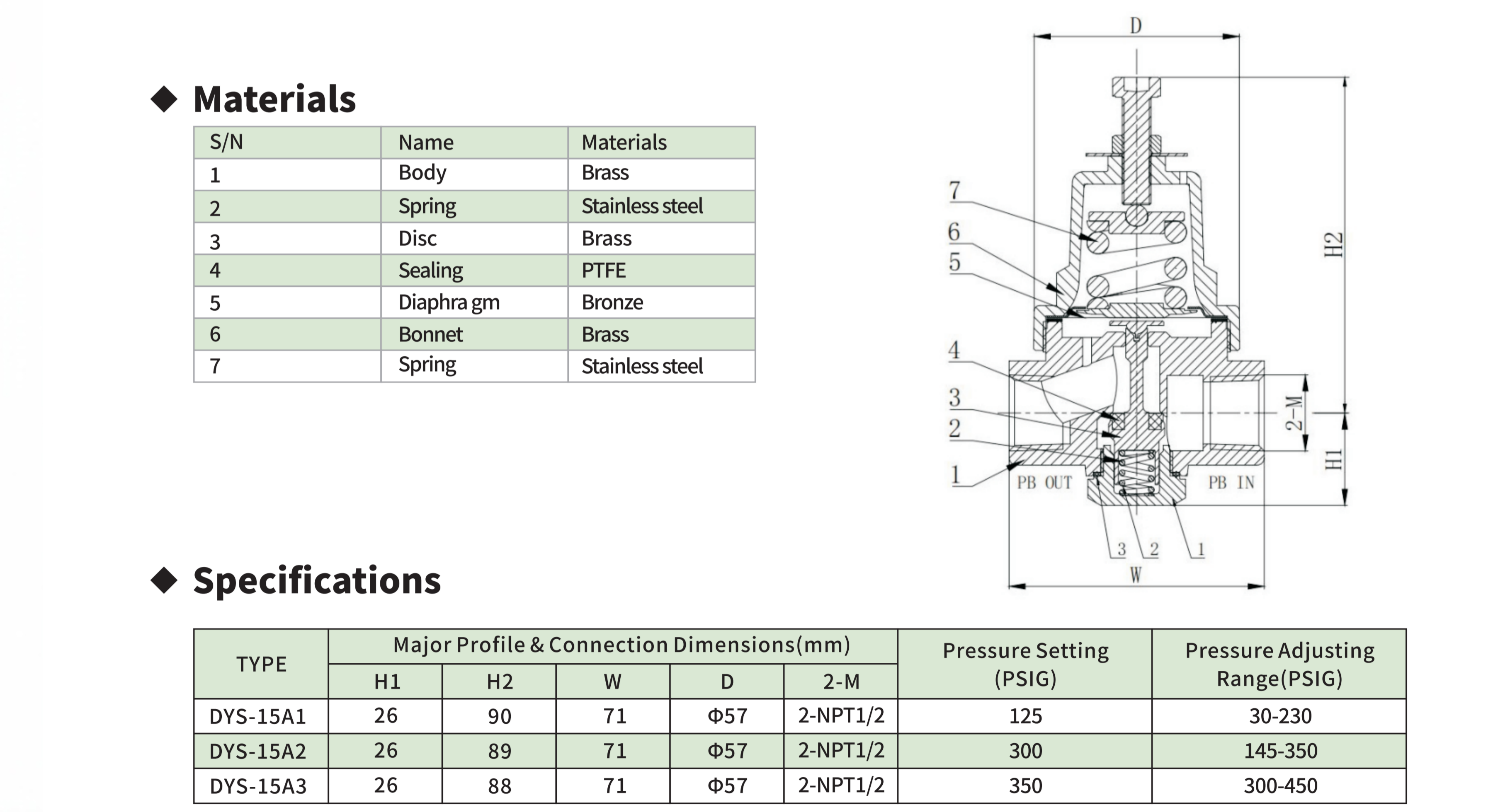
Non-balanced spring reference designs dominate standard applications. They utilize a heavy mechanical spring to set the desired pressure. These regulators leverage upstream pressure to assist in closing the valve. This creates a rapid, bubble-tight shut-off. They keep mechanical complexity low. Maintenance footprints remain small, making them ideal for standard bulk tanks. Field technicians prefer them because they are easy to adjust and rebuild on-site.
Dome-loaded regulators handle extreme flow rates and tight pressure bands. Instead of a mechanical spring, they use trapped gas pressure (the dome) to establish the setpoint. This design eliminates spring rate variations. It provides incredibly flat flow curves. However, dome-loaded setups increase system complexity. They require external pilot regulators and additional tubing, which introduces more potential leak points. We only specify dome-loaded units for high-flow applications where a 5 psi pressure drop is unacceptable.
The choice between spring and dome often comes down to available space and technical capability. Spring regulators are rugged and forgiving. Dome regulators require clean gas and precise pilot adjustments. If your maintenance team lacks experience with pneumatic controls, stick to spring-reference designs. They offer the highest reliability for general industrial gas applications.
Standalone units offer dedicated pressure building. They isolate easily for maintenance without shutting down the entire economizer circuit. Standalone designs typically provide higher maximum flow rates. They utilize larger internal orifices. If a standalone regulator fails, you only replace one component. This modularity appeals to facilities prioritizing high uptime and easy troubleshooting. You can swap a standalone valve in under twenty minutes if you have isolation valves installed.
Combination valves integrate multiple functions into one body. They combine pressure building, economizer, and auxiliary safety features. This architecture drastically reduces the installation footprint. It eliminates multiple threaded connections, minimizing potential leak paths. However, combination valves often sacrifice maximum flow capacity. If one internal component fails, you usually must rebuild or replace the entire multi-functional unit. We see combination valves used heavily on microbulk tanks where space is at a premium.
Feature | Standalone Regulators | Combination Valves |
|---|---|---|
Flow Capacity | High (Larger Orifices) | Moderate (Restricted Internals) |
Installation Footprint | Large (Requires multiple pipes) | Compact (All-in-one body) |
Maintenance Ease | Simple (Isolate and replace) | Complex (Requires full rebuild) |
Leak Paths | Multiple (More threaded joints) | Minimal (Fewer external joints) |
Body materials must withstand extreme thermal contraction. Forged brass and bronze offer excellent performance in standard cryogenic environments. They resist embrittlement and maintain structural integrity. 316 stainless steel provides superior external corrosion resistance. Facilities exposed to harsh weather or coastal salt spray specify stainless steel. Furthermore, stainless steel is often preferred for stringent oxygen-safety suitability. Brass can dezincify in certain chemical environments, making stainless the safer long-term choice.
Soft goods dictate shut-off reliability. PTFE (Teflon) handles low temperatures but suffers from cold flow under heavy mechanical loads. PCTFE (Kel-F) stands as the industry standard. It maintains dimensional stability at cryogenic temperatures. PCTFE resists cold flow and provides exceptional bubble-tight sealing. Metallic seats handle extreme durability needs but rarely achieve the tight shut-off required to prevent slow pressure creep. Always specify PCTFE for pressure builders to prevent the tank from slowly over-pressurizing overnight.
Ambient humidity destroys regulator performance. Continuous high-flow withdrawal pulls massive amounts of heat from the surrounding air. Moisture condenses and freezes on the valve body. This external icing builds up rapidly. It encases the spring housing and restricts the movement of internal components. Severe icing physically locks the regulator in an open or closed position. We have seen ice blocks the size of basketballs form around poorly specified regulators.
Design mitigations prevent mechanical binding. Manufacturers utilize extended stems to isolate the cold liquid from the spring housing. Specific weep hole placements allow trapped moisture to drain before freezing. Thermal standoff designs keep the sensing diaphragm warmer than the flowing cryogen. These features ensure the regulator operates freely, even when encased in a block of external ice. If you operate in high-humidity environments like the Gulf Coast, extended stems are mandatory.
You can also mitigate icing through piping design. Install the regulator as far from the liquid withdrawal point as practical. Use uninsulated copper or stainless tubing to allow some ambient heat absorption before the fluid hits the valve. Never insulate the pressure builder itself. It needs ambient heat to function correctly. Insulating the valve traps the cold and accelerates internal freezing.
Operational security demands strict control over pressure settings. Operator tampering poses a massive risk. Inexperienced personnel often crank up the pressure builder to increase flow. This pushes the cryogenic storage tank closer to its maximum allowable working pressure (MAWP). It triggers relief valves and wastes massive amounts of product through venting. A single operator adjusting a valve with a wrench can cost a facility thousands of dollars in lost gas.
Compliance relies on engineered limits. Facility managers increasingly specify factory-set, tamper-proof regulators. These units arrive pre-calibrated to the exact tank specifications. They feature pinned or sealed adjustment screws. This prevents unauthorized field adjustments. Factory-set configurations maintain safety margins and ensure the system operates exactly as the original engineers intended. If a process requires more pressure, you must evaluate the entire system, not just turn a screw.
Cryogenic components endure severe mechanical stress. Diaphragms flex constantly under extreme cold. Springs fatigue over thousands of cycles. Soft seats absorb the impact of rapid shut-offs. These wear components dictate the Mean Time Between Failures (MTBF). Regular inspection of these parts prevents catastrophic blow-by and ensures stable pressure delivery. Waiting for a failure before performing maintenance guarantees production downtime.
Serviceability impacts facility downtime. Some regulators allow in-line maintenance. Technicians can unbolt the top works and replace the diaphragm and seat without cutting pipes. Others require complete removal from the piping circuit. OEM rebuild kits provide reliable solutions. Replacing soft goods every few years extends the lifespan of the heavy brass or stainless steel body indefinitely. Always keep a spare rebuild kit on the shelf for critical applications.
Orientation dictates performance. Install regulators with the spring housing pointing upwards. This prevents liquid cryogen from pooling inside the sensing chamber. Liquid pooling causes erratic pressure sensing and severe internal freezing. Proper orientation ensures only gas interacts with the diaphragm, providing smooth and accurate pressure regulation. Installing a valve sideways or upside down guarantees premature failure.
Clearances protect the internal soft goods. Install cryogenic strainers upstream of the regulator. Strainers catch pipe scale, Teflon tape debris, and brazing slag. If particulate matter enters the regulator, it scores the PCTFE seat. Even a microscopic scratch causes the valve to leak. Leave adequate spacing around the valve to allow technicians room for wrenches during future maintenance.
Purge all piping with dry nitrogen before installation to remove moisture and debris.
Install a 100-mesh cryogenic strainer immediately upstream of the regulator inlet.
Mount the valve with the spring housing perfectly vertical.
Apply oxygen-compatible thread sealant to all NPT connections.
Leak test all joints with a cryogenic leak detector fluid before introducing liquid.
Oxygen service requires absolute cleanliness. You must mandate adherence to CGA G-4.1 or equivalent standards. Any hydrocarbon residue inside the regulator creates a severe ignition hazard when exposed to liquid oxygen. Manufacturers clean, assemble, and bag oxygen-service regulators in dedicated cleanrooms. Never install a standard industrial regulator into an oxygen circuit. Even a fingerprint contains enough oil to cause a flash fire in a high-pressure LOX line.
Global certifications ensure legal compliance. Specify regulators that meet ASME B31.3 standards for process piping. In Europe, valves must comply with the Pressure Equipment Directive (PED) and Transportable Pressure Equipment Directive (TPED). Verifying these certifications protects your facility from liability and ensures the components survive rigorous safety inspections. Inspectors will shut down a system if they find uncertified valves in the pressure build circuit.
Calculate your exact Cv requirements based on peak flow rates and gas specific gravity before purchasing any hardware.
Audit your current pressure build circuits to ensure all regulators are installed with the spring housing pointing vertically.
Replace any field-adjustable regulators with factory-set models if you experience frequent unauthorized pressure changes.
Implement a preventative maintenance schedule to rebuild or replace PCTFE seats every three to five years.
A: Pressure builders increase tank pressure by routing liquid through a vaporizer and sending gas back into the headspace. Economizers reduce excess pressure by routing high-pressure headspace gas directly into the withdrawal line, prioritizing gas usage before building new pressure.
A: Freezing occurs due to continuous high-demand withdrawal that exceeds the vaporizer's capacity. It pulls extreme cold into the valve body. Ambient moisture then condenses and freezes on the exterior. Undersizing the regulator also exacerbates this by creating excessive pressure drops.
A: No. Factory-set models are designed to be tamper-evident. They are calibrated to specific safety tolerances. End-users should never adjust them. Altering the setpoint risks exceeding the tank's maximum allowable working pressure and triggering safety relief valves.
A: You need four main variables: the maximum required flow rate, the specific gravity of the gas, the minimum inlet pressure from the tank, and the allowable pressure drop across the valve. Plug these into a standard gas Cv formula.
A: Both materials are acceptable if they are strictly cleaned for oxygen service according to CGA G-4.1. However, stainless steel offers superior external corrosion resistance, making it better for harsh environments or coastal installations.
A: Standard preventative maintenance schedules dictate rebuilding or replacing soft goods every 3 to 5 years. This depends heavily on cycle frequency, flow rates, and the operating environment. Regular inspections prevent unexpected seat leakage and diaphragm failure.

 yongy0223@gmail.com
 +86-17693104145
 Lanzhou New Area, Lanzhou City, Gansu Province, on the second floor to the east of New Harbor Road, to the east of Building Materials Road No. 2, to the west of Qilian Mountain Avenue (Jingqi Road)


