


Views: 0 Author: Site Editor Publish Time: 2026-09-02 Origin: Site


Cryogenic storage reliability dictates facility success. Compromised temperature stability causes catastrophic sample loss, triggers production downtime, and creates severe safety liabilities. Facility managers face a strict balancing act. They must weigh storage capacity against footprint constraints and evaluate acceptable boil-off rates. These metrics must align strictly with workflow demands. You must match vessel structural architecture directly to application requirements. Solutions range from static dewars to high-capacity pressurized vessels. Each serves specific dispensing, transport, and long-term storage needs. Selecting the wrong vessel architecture guarantees operational bottlenecks, accelerates liquid nitrogen waste, and introduces unnecessary hazards into the workspace. Understanding the engineering behind these vessels prevents procurement mistakes. We will evaluate the exact specifications required to maintain thermal stability across various industrial and laboratory environments.
Workflow Dictates Architecture: Non-pressurized dewars are strictly for static storage and manual retrieval, whereas self-pressurized vessels are mandatory for automated dispensing and continuous supply lines.
Boil-Off Rates Drive OpEx: The Normal Evaporation Rate (NER) is a primary cost driver; prioritizing advanced vacuum insulation technology reduces long-term liquid nitrogen consumption.
Mobility Requires Specific Engineering: Transporting cryogens requires specialized internal baffling and reinforced neck tubes to prevent structural failure and hazardous spills during transit.
Phase Storage Matters: Choosing between liquid-phase and vapor-phase storage is critical for biobanking to balance thermal stability with the prevention of cross-contamination.
Facility Compliance is Non-Negotiable: High-capacity industrial tanks require rigorous adherence to pressure vessel codes (e.g., ASME, PED) and strict facility ventilation protocols to mitigate asphyxiation risks.
Calculate static hold times using supply delivery schedules. Factor in emergency buffer requirements. A facility receiving weekly deliveries needs a 14-day hold time minimum. This covers missed shipments. Weather events often delay bulk deliveries. Determine true working capacity versus gross volume. Gross volume measures the entire inner vessel. Working capacity accounts for headspace. It leaves room for vapor expansion. Never fill a vessel to absolute gross capacity. Overfilling causes liquid to enter the vent lines. This damages pressure relief valves.
Calculate your dynamic evaporation rate. Dynamic rates account for lid openings and liquid withdrawals. Static hold time only measures undisturbed evaporation. Real-world usage always reduces the theoretical hold time. If a laboratory consumes 10 liters per day dynamically, a 150-liter vessel provides roughly 15 days of working supply. However, you must account for the normal evaporation rate (NER). If the NER is 2% per day, you lose an additional 3 liters daily just to ambient heat transfer. This reduces the actual working time to under 12 days. Engineers must size the vessel to accommodate both dynamic withdrawal and static NER while maintaining a 20% safety margin.
Biological samples require specific phase storage. Liquid phase offers maximum thermal stability. Samples remain submerged at -196 degrees Celsius. Vapor phase prevents cross-contamination in biobanking. Samples sit above the liquid pool. They rely on cold vapor for preservation. Choose vapor phase for diverse sample inventories. Evaluate manual decanting versus piped distribution. Transition to pressurized distribution when daily access exceeds manual safety limits.
Active dispensing eliminates heavy lifting. It reduces splash hazards. Piped systems require continuous pressure maintenance. Manual dewars rely on operators pouring the liquid. Pouring introduces human error. It increases the risk of cryogenic burns. Automated dispensing ensures precise volume control. When designing a facility layout, map out the exact distance between the primary storage vessel and the end-use stations. If operators must transport liquid more than 50 feet, manual decanting becomes a severe safety liability. At this threshold, install vacuum-jacketed piping connected to a pressurized supply. This eliminates the need for personnel to push heavy dewars across uneven floor surfaces.
Standard open-neck dewars serve static applications. Manufacturers build them using lightweight aluminum or clinical-grade stainless steel. Aluminum suits general lab use. It keeps the empty weight manageable. Stainless steel provides enhanced durability for heavy-duty cycles. It resists dents from accidental impacts. These units handle small-scale laboratory sample preservation. They excel at cryopreservation of cells. Use them for low-frequency access storage. They require manual retrieval methods. Operators use specialized ladles or extraction racks.
The neck tube utilizes composite materials like G10 fiberglass. This prevents heat transfer from the outer shell to the inner vessel. Open-neck designs prioritize easy access over absolute thermal efficiency. The structural integrity of the neck tube determines the lifespan of a static dewar. G10 fiberglass offers excellent tensile strength while maintaining a low thermal conductivity profile. However, aggressive manual extraction of sample racks can score the inner surface of the neck tube. Over time, these micro-abrasions compromise the vacuum seal. Train personnel to lift racks vertically without dragging them against the composite material.
Mobility demands structural reinforcements. Transport vessels feature internal support systems. They use spill-proof designs. Dry shippers utilize hydrophobic absorbents. This foam absorbs the liquid nitrogen. It prevents liquid spills during transit. A mobile lab liquid nitrogen tank requires high vibration resistance. Dynamic hold times drop during movement. Liquid sloshing increases heat transfer. Transport units must meet DOT and ADR compliance standards. Engineers reinforce the neck tube to handle lateral G-forces.
Standard static dewars will fracture under transport stresses. Mobile units often include heavy-duty roller bases. They feature locking casters for secure positioning. Tie-down points ensure stability inside transport vehicles. When specifying a transport vessel, verify the dynamic NER rating. A tank that holds liquid for 30 days while stationary might only hold it for 14 days in transit. The constant agitation of the fluid breaks the thermal stratification inside the vessel. This forces colder liquid against the slightly warmer upper walls, accelerating boil-off. Always pre-chill dry shippers for 24 hours before loading biological samples. This ensures the hydrophobic foam reaches maximum saturation and stabilizes the internal temperature.
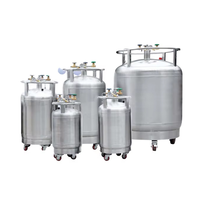
Pressurized systems eliminate manual pouring. A self-pressurized liquid nitrogen tank uses pressure-building circuits. These circuits utilize ambient heat. They vaporize a small amount of liquid. This creates internal head pressure. The pressure forces liquid out through withdrawal valves. Use cases include medical cryotherapy and biological research. They supply manifold systems in mid-sized facilities. Operators set the operating pressure using a regulator. Typical settings range from 22 psi to 50 psi. Higher pressure allows faster liquid withdrawal. It also pushes liquid through longer piping runs.
These tanks feature liquid level gauges. They eliminate the need for manual dipsticks. The pressure-building coil sits at the bottom of the vessel, exposed to ambient air outside the vacuum jacket. When the operator opens the pressure-building valve, liquid gravity-feeds into this coil. The ambient heat instantly vaporizes the liquid, expanding it by a factor of 696. This gas routes back into the top headspace of the inner vessel, driving the pressure up. Once the target pressure is reached, the regulator automatically closes the circuit. This mechanical loop requires no external power, making it highly reliable for continuous industrial operations.
Heavy manufacturing requires microbulk and bulk storage. An industrial self-pressurized liquid nitrogen tank holds hundreds to thousands of liters. These vessels optimize long-term industrial storage. Aerospace sectors use them for shrink-fitting parts. Food and beverage plants require them for flash freezing. Pharmaceutical facilities depend on them for lyophilization. Integrate these vessels with external vaporizers. Connect them to vacuum-jacketed piping networks. Bulk tanks sit on dedicated concrete pads. Delivery trucks connect directly to the fill manifold.
Telemetry systems alert suppliers when levels drop. This ensures uninterrupted production cycles. Industrial vessels utilize dual pressure relief manifolds. This allows maintenance without taking the tank offline. Siting a bulk vessel requires extensive civil engineering. The concrete pad must support the fully loaded weight of the vessel, which can exceed tens of thousands of pounds. You must also install crash bollards to protect the tank from forklift and delivery truck impacts. The dual pressure relief manifold uses a diverter valve to route pressure to one set of relief valves while isolating the other. This allows technicians to remove, test, and replace PRVs without venting the entire tank or halting facility production.
Core structural components dictate performance. Inner and outer vessel dynamics isolate the cryogen. The neck tube plays a thermodynamic role. It minimizes heat transfer from ambient air. Material selection impacts structural longevity. Aerospace-grade aluminum offers a lighter footprint. Stainless steel delivers superior thermal efficiency. It resists physical impacts better. The inner vessel must withstand extreme thermal contraction. Welds undergo rigorous X-ray inspection. Micro-fractures in the weld compromise the vacuum.
Outer shells utilize carbon steel in massive bulk tanks. They use stainless steel in cleanroom environments. The surface finish prevents corrosion. It reflects radiant heat away from the vessel. Most high-grade industrial vessels utilize 304L stainless steel for the inner tank. The "L" denotes low carbon content, which prevents carbide precipitation during the welding process. This ensures the welds remain ductile at -196 degrees Celsius. If a manufacturer uses standard 304 stainless, the welds become brittle and prone to fatigue cracking after repeated fill-and-empty cycles. Always request material test reports during the procurement phase to verify the exact alloy composition.
The annular space holds the vacuum. Multi-layer super insulation (MLI) wraps the inner vessel. MLI consists of alternating layers of aluminum foil and fiberglass paper. Chemical getters absorb residual outgassing. Palladium oxide getters trap stray hydrogen molecules. They maintain the vacuum over the tank's lifespan. A high-quality vacuum reaches 10^-5 Torr. Insulation quality correlates directly to NER. Better vacuum retention means lower evaporation rates. This ensures long-term thermal efficiency.
If the vacuum fails, the tank loses its insulating properties immediately. The outer shell will become ice-cold. Rapid boil-off occurs within hours. The application of MLI requires precision manufacturing. If the layers are wrapped too tightly, they conduct heat through physical contact, defeating the purpose of the insulation. If wrapped too loosely, they fail to block radiant heat transfer effectively. Manufacturers must achieve the perfect tension during the wrapping process. Additionally, the chemical getters only activate after the tank is sealed and evacuated. They act as an insurance policy against microscopic outgassing from the metal surfaces over a 10-to-15-year operational lifespan.
Safety relies on pressure control. Pressure relief valves (PRVs) vent excess gas. Rupture discs provide fail-safe backup. If the PRV fails, the rupture disc bursts. This prevents catastrophic vessel explosion. Pressure building regulators maintain operational head pressure. Liquid withdrawal valves manage fluid transfer. Vent valves handle gas exhaust. Operators must balance these valves. This manages operational safety and efficiency. High-quality valves utilize extended stems. This keeps the handwheel away from the freezing zone. It prevents operator frostbite.
Teflon seals withstand cryogenic temperatures without cracking. Brass and stainless steel dominate valve construction. Valve orientation matters during installation. Liquid withdrawal valves must sit at the lowest point of the internal dip tube to ensure complete emptying of the vessel. Vent valves connect to the highest point of the headspace. When filling a pressurized cylinder, the operator opens the vent valve to release internal pressure, allowing incoming liquid to displace the gas. If the vent valve is undersized, the filling process takes significantly longer, and the delivery driver may waste liquid nitrogen through excessive transfer boil-off.
Continuous monitoring prevents catastrophic loss. Sensors track liquid level and temperature gradients. They monitor internal pressure. Differential pressure gauges calculate the liquid level accurately. Integrate these sensors with Laboratory Information Management Systems (LIMS). Connect them to Building Management Systems (BMS). This enables automated alerts. Staff receive notifications before critical failures occur. Modern telemetry uses 4-20mA output signals. PT100 RTD sensors provide precise temperature data.
Cloud-based dashboards allow remote monitoring. You can track consumption trends over time. This data optimizes delivery schedules. It identifies anomalous boil-off rates early. Differential pressure gauges measure the pressure difference between the bottom of the liquid column and the top headspace. Because liquid nitrogen has a known density, the gauge translates this pressure differential into an accurate liquid level reading. However, these gauges require periodic calibration. If the capillary tubes connecting the gauge to the tank develop a leak, the reading will falsely indicate a full tank. Always cross-reference electronic telemetry with manual vent checks if you suspect a sensor malfunction.
Tank Architecture | Primary Use Case | Operating Pressure | Dispensing Method |
|---|---|---|---|
Open-Neck Dewar | Static sample storage, cell cryopreservation | Ambient (0 psi) | Manual decanting / ladles |
Dry Shipper | Biological sample transport | Ambient (0 psi) | Vapor phase only (no liquid) |
Self-Pressurized Cylinder | Lab manifold supply, cryotherapy | 22 - 50 psi | Automated valve withdrawal |
Industrial Bulk Vessel | Heavy manufacturing, food freezing | 50 - 150+ psi | Vacuum-jacketed piping network |
Safety Component | Primary Function | Standard Material | Inspection Interval |
|---|---|---|---|
Pressure Relief Valve (PRV) | Vents excess gas to maintain safe operating pressure | Brass / Bronze | Annually |
Rupture Disc | Fail-safe burst mechanism if PRV fails | Stainless Steel | Replace every 3-5 years |
Extended Stem Valve | Controls liquid withdrawal while preventing frostbite | Stainless Steel / Teflon | Bi-annually for leaks |
Oxygen Depletion Monitor | Detects low oxygen levels in the storage room | Zirconium Oxide Sensor | Quarterly calibration |
Analyze the trade-off between purchasing lower-efficiency tanks versus premium tanks with superior vacuum retention. High-efficiency vessels drastically reduce ongoing liquid nitrogen replenishment requirements. A tank with a 1.5% NER will consume significantly less gas over a decade compared to a tank with a 3% NER. This reduction in gas consumption directly impacts facility logistics. Fewer deliveries mean less disruption to the loading dock. It reduces the labor hours spent escorting delivery personnel and monitoring the fill process.
Prioritize vacuum integrity over initial volume. A slightly smaller, highly efficient tank often outperforms a larger, poorly insulated vessel. Evaluate the warranty on the vacuum seal. Industry standards typically offer a 5-year vacuum warranty on standard cylinders and up to 10 years on premium bulk vessels. If a tank loses its vacuum after three years, the operational disruption of swapping the vessel far outweighs any initial procurement savings.
Evaluate the floor space requirements of wide-neck storage freezers versus tall, narrow pressurized cylinders. Wide-neck freezers consume massive amounts of floor space. They require clearance on all sides for lid opening and sample retrieval. Tall cylinders maximize vertical space. They fit into tighter utility closets or manifold rooms. Accommodating larger vessels often requires reinforced flooring. A 1,000-liter tank exerts massive point loads on the concrete slab. You may need to widen access doors or remove door frames to maneuver the vessel into position.
Always measure the entire travel path from the loading dock to the final installation site. Check the weight capacity of freight elevators. Verify the height clearance of all doorways. A common failure in facility planning is ordering a high-capacity vessel that cannot pass through a standard 36-inch commercial door. In these cases, facilities must either breach a wall or return the unit for smaller, modular cylinders.
Cryogens present severe risks. Oxygen depletion causes rapid asphyxiation. Liquid nitrogen expands at a ratio of 696:1 when vaporized. A small spill displaces massive amounts of oxygen. Contact causes severe cryogenic burns and frostbite. Establish strict protocols for safe filling. Transfer operations carry thermal shock risks. Bulk-to-dewar transfers create splash hazards. Always use phase separators on the dispensing hose. Mandatory mitigation strategies include personal protective equipment (PPE). Operators must wear face shields and cryogenic gloves. Install oxygen depletion monitors 18 inches above the floor. Enforce standard operating procedures (SOPs). Never allow untrained personnel to operate cryogenic valves.
Follow a strict sequence during manual filling operations:
Verify the receiving vessel is completely depressurized before connecting transfer hoses.
Inspect the transfer hose for cracked stainless steel braiding or damaged brass fittings.
Attach the phase separator to the end of the hose to diffuse the liquid stream and prevent splashing.
Open the supply valve slowly to allow the transfer hose to cool down gradually, preventing thermal shock.
Monitor the vent exhaust; a distinct change in the sound of the venting gas indicates the receiving vessel is full.
Identify early warning signs of vacuum failure. Excessive sweating or frosting on the outer shell indicates trouble. Rapid liquid loss confirms vacuum degradation. Implement a realistic preventative maintenance schedule. Include annual PRV testing. Use a soap bubble test to check for valve leaks. Calibrate liquid level gauges regularly. Assess vacuum re-pumping feasibility. Some vessels allow vacuum restoration through a dedicated pump-out port. Others require complete replacement. Inspect the outer shell for dents or corrosion. Physical damage often precedes vacuum loss. Keep the tank environment dry to prevent ice buildup on control components.
Ice buildup on the pressure-building regulator can freeze the internal diaphragm, causing the tank to over-pressurize. If you observe heavy ice accumulation, do not chip it away with a hammer. Striking frozen brass valves will shatter them. Instead, use a heat gun on a low setting or warm water to melt the ice safely. Document all maintenance activities in a dedicated facility logbook to track the degradation of components over time.
Indoor storage demands specific architectural requirements. Active exhaust ventilation is mandatory. Calculate room volume against maximum potential gas expansion. Ensure ventilation systems can handle a catastrophic spill. Position exhaust vents near the floor. Nitrogen gas is heavier than air. It pools at ground level. Interlock the ventilation system with the oxygen monitors. If oxygen drops below 19.5%, the exhaust fans must activate automatically. Install visual and audible alarms outside the storage room. Staff must know the room is unsafe before entering. Adhere to local fire codes and compressed gas association guidelines.
A standard 10x10x10 foot room contains 1,000 cubic feet of air. Spilling just 10 liters of liquid nitrogen produces roughly 245 cubic feet of pure nitrogen gas. This instantly drops the oxygen concentration in the room to lethal levels. Passive ventilation through door louvers is entirely insufficient. You must install forced-draft exhaust fans capable of achieving at least six air changes per hour (ACH) under normal conditions, and up to 15 ACH during an alarm state.
The optimal liquid nitrogen tank depends entirely on application workflow. You must balance storage versus supply. Phase storage requirements dictate inner geometry. Facility infrastructure limits vessel size. Do not compromise on vacuum quality or safety features. Follow a step-by-step shortlisting logic. First, calculate required volume and hold time based on delivery schedules. Second, determine if the process requires pressurized dispensing or static storage. Third, filter options by mobility and footprint constraints. Finally, validate the final choice against safety and compliance standards.
Conduct a facility ventilation audit to ensure exhaust systems meet the required air changes per hour for your specific room volume.
Calculate your historical dynamic consumption rates to size the new vessel accurately without overpaying for unused capacity.
Consult a cryogenic engineering specialist to specify the exact vacuum-jacketed piping and manifold requirements for your layout.
Establish an automated telemetry baseline for the new system to track normal evaporation rates before introducing critical biological samples.
A: Standard dewars are non-pressurized open-neck vessels used for manual sample storage and retrieval. Self-pressurized tanks are sealed vessels featuring internal pressure-building circuits. These circuits vaporize a small amount of liquid to create head pressure, which automatically pushes liquid out through dispensing valves for continuous supply.
A: Static hold time ranges from a few weeks to several months. It depends heavily on the tank's total volume, neck diameter, and vacuum integrity. Real-world dynamic hold time is always shorter, as frequent lid openings and liquid withdrawals accelerate the evaporation rate significantly.
A: Maintenance requires strict annual inspections. Technicians must test pressure relief valves and check the outer shell for vacuum degradation, indicated by excessive frosting. Routine maintenance also includes calibrating differential pressure liquid level gauges, testing telemetry sensors, and inspecting withdrawal valves for dangerous ice buildup.
A: Transport requires strict adherence to DOT regulations. Vehicles need active ventilation and secure tie-down points to prevent tipping. Biological transport requires dry shippers with hydrophobic absorbents to prevent liquid spills. Never transport open-neck dewars in enclosed passenger compartments due to the severe asphyxiation risk.
A: The Normal Evaporation Rate (NER) defines acceptable boil-off and depends on tank size. Small static dewars may lose 0.1 to 0.2 liters per day. Large industrial tanks lose higher absolute volumes but maintain a much lower percentage loss, often under 1.5% of their total capacity daily.
A: Indoor venting requires dedicated infrastructure. You must pipe the vent exhaust directly to the exterior of the building. The storage room requires active exhaust ventilation positioned near the floor. You must also install oxygen depletion monitors to trigger alarms and fans if gas accumulates.

 yongy0223@gmail.com
 +86-17693104145
 Lanzhou New Area, Lanzhou City, Gansu Province, on the second floor to the east of New Harbor Road, to the east of Building Materials Road No. 2, to the west of Qilian Mountain Avenue (Jingqi Road)


