


Views: 0 Author: Site Editor Publish Time: 2026-07-15 Origin: Site


The continuous financial and operational drain of vented head gas in liquid cylinder and bulk storage operations demands immediate attention. Natural heat leak causes liquid to vaporize, building pressure within a cryogenic tank. Without proper regulation, this excess pressure vents directly to the atmosphere. This results in direct product loss, safety hazards, and compliance issues. Upgrading to modern cryogenic economizers allows facilities to automatically prioritize vapor withdrawal over liquid withdrawal. You capture otherwise wasted gas, stabilize tank pressure, and streamline manifold architecture. Relying on standard relief valves for pressure management is an outdated practice that drains resources. Implementing an economizer circuit transforms excess head gas into usable product, ensuring your storage system operates efficiently and safely while maintaining optimal delivery pressure for downstream applications.
Zero-Loss Operation: Economizer circuits utilize excess head gas pressure for downstream processes, preventing atmospheric venting and recovering product costs.
Architectural Efficiency: Modern economizer designs integrate laterally with pressure regulators, reducing component weight by up to 40% and minimizing potential leak points.
System Compatibility: Upgrading requires precise matching of economizer pressure settings with existing cryogenic valves, pressure building circuits, and the specific cryogenic storage tank specifications.
Measurable ROI: The payback period for modern economizers is directly tied to the cost of the specific cryogenic fluid (e.g., Argon, Helium, Nitrogen) and the facility's intermittent usage patterns.
Establishing the baseline for acceptable pressure ranges and acceptable loss rates in cryogenic storage requires a clear understanding of thermal dynamics. Facilities must accurately frame the problem before implementing hardware upgrades. You cannot manage what you do not measure, and unmonitored pressure spikes lead directly to atmospheric venting. Understanding the physical mechanics of your storage vessels provides the foundation for effective pressure control.
Normal evaporation rates (NER) in insulated cylinders dictate the baseline pressure increase. No vacuum insulation is perfect. Heat transfers through the inner vessel supports, piping connections, and the vacuum annulus itself. As the cryogenic liquid absorbs this ambient heat, it boils and expands into gas. This gas accumulates in the vapor space at the top of the vessel, steadily driving up internal pressure.
Intermittent gas usage exacerbates pressure buildup in the vapor space. When a facility draws gas continuously, the withdrawal process naturally removes pressure. However, during idle periods like weekends or overnight shifts, the liquid continues to absorb heat. The pressure rises until it hits the setpoint of the primary relief valve. Heat leak dynamics differ significantly between portable liquid cryogenic cylinders and stationary, vacuum-insulated bulk storage vessels. Dewars experience more rapid pressure spikes due to their smaller volume-to-surface-area ratio. Bulk tanks have thicker insulation profiles and lower relative surface areas, but the sheer volume of gas lost during a venting event is much higher.
Vessel Type | Typical Capacity | Average NER (% per day) | Venting Risk Profile |
|---|---|---|---|
Portable Liquid Cylinder (Dewar) | 160L - 230L | 1.5% - 2.0% | High (Rapid pressure spikes during idle shifts) |
Microbulk Storage Tank | 1000L - 3000L | 0.8% - 1.2% | Medium (Moderate pressure rise over weekends) |
Stationary Bulk Tank | 3000L - 10000L+ | 0.3% - 0.5% | Low to Medium (High volume loss when venting occurs) |
Quantifying the cost of vented gas through standard relief valves reveals substantial operational waste. Every cubic foot of gas vented to the atmosphere represents money spent on production, transportation, and storage that yields zero return. For high-value gases like helium or argon, these losses devastate operating margins. Facilities often underestimate the cumulative financial impact of a relief valve hissing intermittently throughout the day.
Safety and environmental compliance risks escalate when venting inert or reactive gases in enclosed spaces. Oxygen enrichment creates severe fire hazards, turning normally non-combustible materials into highly flammable hazards. Nitrogen or argon venting displaces ambient oxygen, creating invisible asphyxiation zones. Managing these risks requires strict atmospheric monitoring and robust pressure management protocols. Relying on a safety relief valve as a primary pressure control mechanism violates basic safety engineering principles.
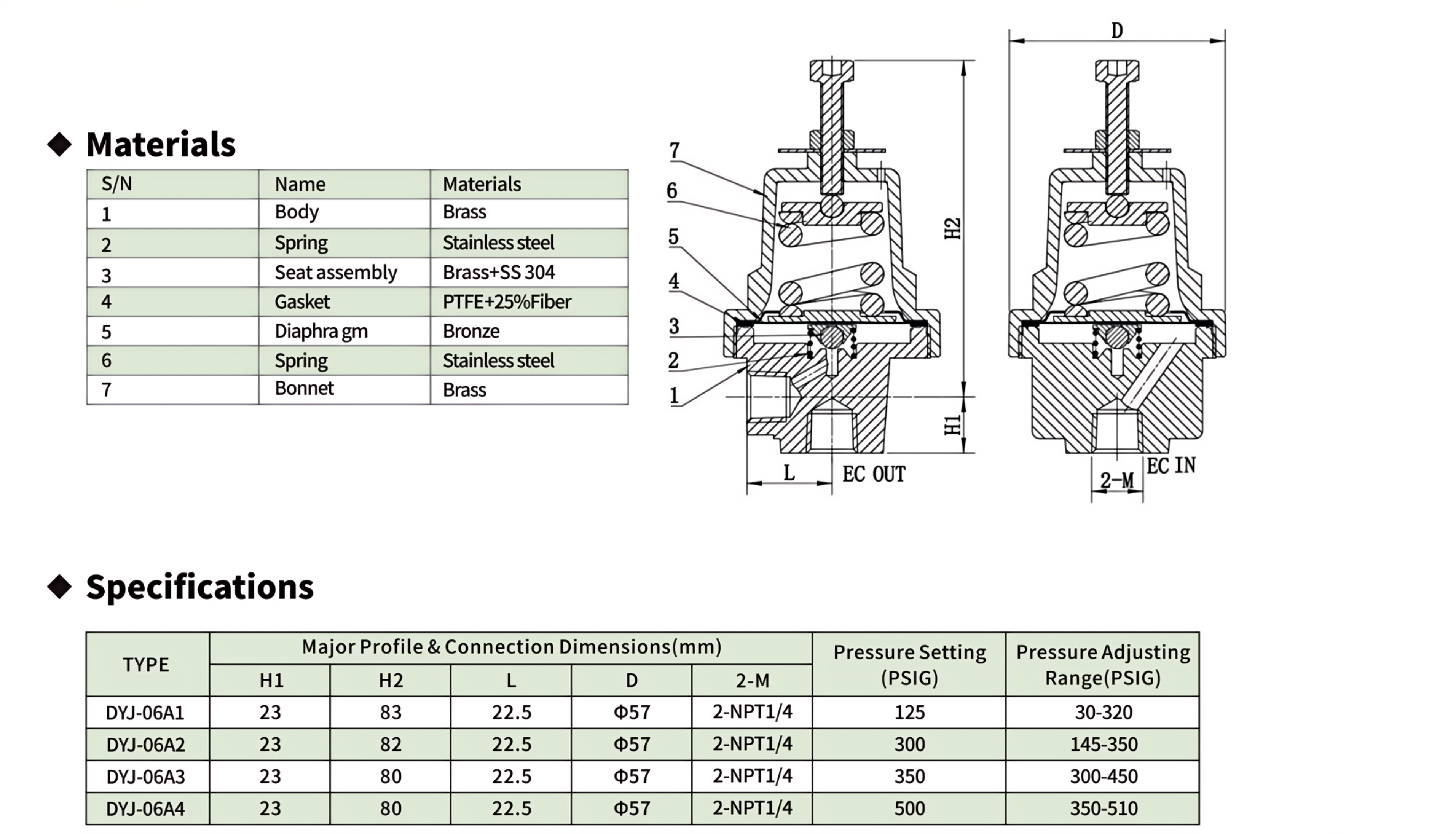
Comparing legacy standalone economizers with modern, integrated regulator-economizer combinations highlights significant advancements in fluid control technology. The shift from reactive pressure relief to proactive pressure utilization defines modern cryogenic management.
The economizer valve opens at a predetermined setpoint to route high-pressure vapor into the primary use line. This mechanism of action directly addresses pressure buildup without atmospheric venting. When the tank pressure exceeds the economizer setting, the valve lifts, allowing the head gas to bypass the liquid withdrawal dip tube. The downstream process consumes this excess vapor instead of drawing fresh liquid from the bottom of the tank.
Preservation of liquid inventory for sustained operations ensures maximum yield from every delivery. By burning off the head gas first, the system naturally lowers the internal tank pressure back to a safe operating range. Once the pressure drops below the economizer setpoint, the valve closes, and the system resumes normal liquid withdrawal through the vaporizer. This automatic toggling between liquid and vapor withdrawal creates a self-regulating ecosystem that virtually eliminates the need for atmospheric venting.
Analysis of modern design improvements reveals that lateral economizer ports drastically reduce envelope space. Legacy systems required complex manifolds with separate pressure building regulators, economizer valves, check valves, and extensive copper or stainless steel tubing. This spiderweb of piping consumed valuable space on the tank exterior and complicated maintenance access.
The evolution from multi-valve configurations to integrated ECL-style layouts and combined pressure building/economizer valves simplifies the entire manifold. Modern combination valves house both the pressure building and economizing functions within a single forged body. This reduction of overall manifold weight often reaches 40% compared to legacy brass configurations. Minimizing threaded connections directly reduces potential leak points and simplifies piping. Fewer joints mean fewer opportunities for vibration-induced leaks or thread sealant failures.
Maintaining consistent delivery pressure to downstream applications prevents process interruptions. Laser cutting operations, medical gas delivery, and food freezing processes require stable, predictable gas flow. Fluctuating tank pressures cause erratic flow rates, leading to poor cut quality, inconsistent freezing, or medical supply alarms. An economizer smooths out these pressure peaks, delivering a steady supply to the final point of use.
Reducing the frequency of safety relief valve actuation extends the lifespan of critical cryogenic valves and maintains system integrity. Relief valves are designed for emergency overpressure protection, not daily pressure regulation. Repeated actuation wears down the soft seating materials, leading to premature failure and continuous weeping. By keeping the tank pressure below the relief valve setpoint, the economizer protects these critical safety devices.
A rigorous framework for specifying the correct economizer ensures optimal performance for specific industrial applications. You must match the hardware to the exact physical and chemical demands of your gas system.
Assessing materials such as bronze, stainless steel, and PTFE components guarantees compatibility with specific gases like Oxygen, Nitrogen, Argon, and CO2. Oxygen service requires strict adherence to material selection to prevent ignition in oxygen-enriched environments. Stainless steel offers superior corrosion resistance for harsh industrial environments, while bronze provides excellent thermal properties for standard inert gas applications. The internal diaphragms and seat materials must withstand extreme temperature cycling without embrittlement.
Matching Cv (flow coefficient) ratings to the facility's peak withdrawal requirements prevents flow restrictions during high-demand cycles. An undersized economizer will not flow enough vapor to drop the tank pressure effectively, rendering it useless during rapid pressure spikes. Conversely, an oversized valve may hunt or chatter, causing premature wear on the internal components. You must calculate the maximum standard cubic feet per hour (SCFH) required by your downstream process and select an economizer with a corresponding Cv rating.
The critical relationship between the pressure building regulator, which adds pressure, and the economizer, which reduces excess pressure, dictates system stability. The pressure builder vaporizes liquid and feeds it back into the head space to maintain driving pressure. The economizer bleeds off head space gas to reduce pressure. If these two circuits overlap, they will fight each other, creating a continuous loop of vaporizing and bleeding that destroys efficiency.
Evaluating standalone economizer valves versus integrated combination regulator-economizers determines the ideal circuit architecture. Ensuring appropriate deadband between the two circuits prevents simultaneous operation and erratic flow. The deadband is the pressure gap between the pressure builder shut-off point and the economizer opening point. A properly calibrated deadband ensures the system remains stable and only activates the necessary circuit based on real-time demand.
Verifying PED, ASME, and TPED certifications for the specific jurisdiction is mandatory. Pressure vessels and their associated piping components must meet strict regulatory standards to ensure operator safety. Installing non-certified components voids tank warranties and exposes the facility to severe legal liability in the event of a failure.
Cleaning requirements for oxygen service, such as CGA G-4.1, must be strictly adhered to during procurement and installation. Any hydrocarbon contamination, including standard machining oils or fingerprints, can ignite violently when exposed to high-pressure oxygen. Components must arrive bagged, sealed, and certified clean for oxygen service. Installers must use specialized tools and oxygen-compatible thread sealants to maintain this cleanliness standard throughout the assembly process.
Practical considerations for installation and long-term maintenance dictate the success of any hardware upgrade. Field execution requires precision, proper tooling, and a deep understanding of cryogenic safety protocols.
Space constraints and incompatible piping on legacy tanks present significant installation risks. Older vessels often feature tightly packed manifolds with non-standard thread pitches or obsolete valve bodies. Forcing modern components into these confined spaces without proper planning leads to stressed piping and eventual fatigue failures.
Utilizing compact, combination regulator/economizer units mitigates these challenges. These integrated units require less physical space and fewer piping modifications. Conducting a thorough audit of existing manifold dimensions before procurement ensures proper fitment. Measure the center-to-center distances of existing ports, verify thread types (NPT vs. BSPT), and assess the physical clearance required for wrench access during installation.
Isolating and safely depressurizing the cryogenic storage tank prior to modification prevents hazardous exposure. Never attempt to break a connection on a pressurized cryogenic system. Follow strict lockout/tagout procedures and verify zero pressure using calibrated gauges before beginning work.
Isolate the liquid and vapor withdrawal valves to secure the tank contents.
Vent all residual pressure from the manifold section being modified using dedicated bleed valves.
Remove the legacy components, taking care not to drop debris into the open piping.
Clean all male and female threads using a stainless steel wire brush and approved solvent.
Apply oxygen-compatible PTFE tape to the male threads, leaving the first two threads bare to prevent tape shredding from entering the fluid stream.
Install the new economizer valve, ensuring proper physical orientation. The valve must be installed upright to prevent liquid entrapment and freeze-up in the spring housing.
Tighten connections to the manufacturer's specified torque rating using appropriate backup wrenches to prevent twisting the manifold piping.
Perform a low-pressure pneumatic leak test using dry nitrogen before introducing cryogenic fluid.
Incorrectly setting the economizer pressure too close to the pressure builder setting leads to system inefficiency and erratic flow. If the deadband is too narrow, minor pressure fluctuations will cause the system to rapidly cycle between building pressure and economizing. This wastes gas and accelerates wear on the valve seats.
Following strict manufacturer step-by-step calibration procedures ensures accurate operation. Always set the pressure builder first, allowing the system to stabilize. Then, adjust the economizer setpoint to maintain the required deadband. Utilizing pre-set, tamper-evident models where appropriate eliminates unauthorized adjustments by untrained personnel on the factory floor.
Establishing a preventative maintenance schedule for seat replacement and leak testing sustains operational reliability. Cryogenic valves operate in extreme thermal environments that degrade soft goods over time. PTFE seats and elastomeric diaphragms lose their elasticity and eventually fail to seal against high pressure.
Conduct weekly visual inspections for abnormal frost patterns on the economizer body or downstream piping.
Perform monthly bubble leak checks on all threaded connections using a low-temperature approved leak detection fluid.
Schedule annual seat and diaphragm replacements using OEM rebuild kits.
Verify calibration settings quarterly using a calibrated test gauge.
Identifying the signs of economizer failure allows for rapid intervention. Continuous venting from the primary relief valve indicates the economizer is failing to open or is undersized. Frosting on the economizer line when the tank pressure is below the setpoint indicates a leaking seat that is allowing gas to bypass prematurely.
Conceptual trade-offs between upfront component costs and long-term operational savings drive the procurement decision. Upgrading manifold hardware requires capital expenditure, but the return on investment is highly predictable when based on accurate venting data.
Calculating the volume of gas saved per month based on facility usage patterns quantifies the return on investment. Monitor the frequency and duration of relief valve venting prior to the upgrade. Multiply this vented volume by your bulk gas contract rate to determine the monthly financial loss. In facilities with highly intermittent usage, the recovered gas value often pays for the economizer hardware within the first two quarters of operation.
Factoring in the reduced labor costs associated with simplified installation and fewer leak repairs further validates the upgrade. Integrated combination valves require fewer man-hours to install and maintain. Reducing the number of threaded connections lowers the probability of leaks, saving maintenance teams from conducting emergency repairs during production shifts. The operational stability provided by a properly functioning economizer circuit eliminates the hidden costs of process interruptions and erratic gas delivery.
Audit your current liquid cylinder venting rates to establish a baseline for potential savings. Review existing manifold schematics to identify space constraints and required connection types. Consult with a cryogenic valve specialist to specify the correct pressure settings and flow capacities for your upgrade.
A: It prioritizes the withdrawal of excess head gas over liquid to maintain tank pressure and prevent product loss through the relief valve.
A: A pressure builder vaporizes liquid to increase tank pressure when it is too low. An economizer draws off vapor to reduce tank pressure when it is too high.
A: Yes, provided the pressure ratings match and there is physical space on the manifold. Integrated lateral-port models make retrofitting significantly easier.
A: Typically 15 to 30 psig, depending on the manufacturer and application, to ensure they do not operate simultaneously.
A: They allow for tighter integration with the pressure regulator, reducing the need for extra piping, decreasing overall weight, and eliminating potential leak paths.
A: Routine visual inspections for leaks and frost anomalies should be conducted daily or weekly, with comprehensive testing and potential seat replacement performed annually or per manufacturer guidelines.

 yongy0223@gmail.com
 +86-17693104145
 Lanzhou New Area, Lanzhou City, Gansu Province, on the second floor to the east of New Harbor Road, to the east of Building Materials Road No. 2, to the west of Qilian Mountain Avenue (Jingqi Road)


