| Application Overview
Every cryogenic tank pays an invisible energy tax daily: liquid inside continuously absorbs heat from the environment and evaporates, gradually building vapor pressure. When pressure hits the safety valve's setpoint, excess gas vents to atmosphere — but that gas is not just gas; it is product whose liquefaction and transport costs have already been paid. For small Dewar flasks and LNG vehicle cylinders, this "boil-off tax" can reach 3–8% of daily consumption, depending on ambient temperature and gas-draw intermittency.
The DYJ06A is the device that collects that tax. It draws high-pressure vapor from the tank's gas space before the safety valve cracks open, routing it preferentially to the downstream consumption point. In plain terms: a safety valve opens the spillway when the dam is about to burst; an economizer diverts water to the irrigation channel before the flood arrives.
Unlike the built-in economizer branch in a combi regulator, the DYJ06A is a fully independent functional unit. Its internals are not a diaphragm-driven poppet design — they are a ball-and-seat pair: stainless steel ball + spring + brass seat. This choice matters: an economizer handles clean vapor, not the potentially droplet-laden two-phase flow that a pressure-building regulator must manage. Vapor-phase erosion on a sealing face is far gentler than liquid-droplet impingement, so a spherical contact can replace a planar one, yielding more sensitive low-opening flow modulation.
Seven components make up the unit: brass body, stainless steel ball-cage seat assembly (brass housing + SS304 ball), PTFE + 25% fiber composite gasket, bronze diaphragm, two stainless steel springs, and a brass bonnet. Two NPT 1/4" ports — EC IN to tank vapor space, EC OUT to downstream service line. Four sub-models span 125 to 500 PSIG, all cleaned and degreased for LOX service per CGA G-4.1, 100% factory tested, TSG 23 and GB/T 34530.1 compliant.
| Working Principle
Ball versus seat — control logic reversed from a PB regulator Before understanding the DYJ06A, untangle one easy-to-confuse concept: an economizer's control direction is the inverse of a pressure-building regulator's.
A PB regulator's logic is "tank pressure low → open → inject build-up gas → tank pressure rises" — low pressure is the trigger, opening is the action, the goal is to drive pressure upward.
An economizer's logic is "tank pressure high → open → export high-pressure vapor → tank pressure falls" — high pressure is the trigger, opening is the action, the goal is to drive pressure downward while putting the high-pressure gas to productive use rather than venting it.
Three phases of dynamic operation
Phase I: Low-pressure dormancy. Tank vapor pressure is below setpoint (e.g., 80 PSIG gauge, setpoint 125 PSIG). The force below the diaphragm is insufficient to overcome the spring preload above. The stainless steel ball is pressed firmly onto the brass seat; the EC IN→EC OUT path is fully closed. The tank's overpressure protection remains solely with the safety valve, but the economizer sleeps — at low pressure there is no high-pressure gas to "economize"; downstream consumption relies on liquid vaporization or an external vaporizer.
Phase II:Approaching the blow-down line. Tank pressure crosses setpoint (e.g., 130 PSIG, setpoint 125 PSIG). The diaphragm lifts, transmitting pressure to the ball-seat pair via the push rod. Here lies a subtle transition: the ball does not snap fully open the instant setpoint is crossed. The spring's progressive compression lifts the ball only a microscopic annular gap at first — initially only a thin film of vapor passes. The higher the tank pressure, the greater the diaphragm travel, the higher the ball lifts, the larger the annular gap area, the higher the flow. This is what "adjusting range" means in the spec table: 30–320 PSIG does not mean you can set any point between 30 and 320 — it means this is the proportional modulation band from barely cracked open (30 PSIG) to essentially wide open (320 PSIG).
Phase III:Full-capacity delivery. Tank pressure continues climbing (e.g., 280 PSIG, setpoint 125 PSIG, range ceiling 320 PSIG). The diaphragm is near maximum displacement. The ball is fully off the seat; the annular gap has reached maximum flow area. EC IN→EC OUT passes tank-top vapor to the downstream service line in a near-straight-through posture. The tank pressure is now clamped below the safety valve blow-down line — not by venting, but by transferring energy into useful work.
The design intent of the ball-and-seat pair
Why a ball for the economizer when PB regulators use a disc? Because a ball's initial contact on its seat is a circular line (an infinitesimally thin ring), while a disc on a flat seat forms a full circular area. The line-contact seal at low lift generates non-linear flow-area growth — a ball lifted 0.01 mm creates an annular gap area far larger than the cylindrical curtain area of a flat disc lifted the same distance. This geometric property gives the ball-and-seat pair significant flow from a barely-open position, precisely matching the economizer's application need: once tank pressure exceeds setpoint, a rapid vapor path from tank top to downstream must be established without hesitation.
Additionally, vapor contains no liquid droplets, so abrasive wear risk is minimal. The ball-and-seat pair's only wear source is contact fatigue from repeated cycling. The hardness gap between the SS304 ball and the brass seat (~200 HB vs. ~80 HB) ensures virtually all wear occurs on the brass side, manifesting as microscopic seat-face indentation. This indentation is self-limiting under normal service: the deeper the seat recesses, the larger the ball-seat contact area, the lower the unit stress, the slower the wear rate — eventually reaching a stable plateau.

|
Factory Shoot

|
Application Video
|
Product parameters
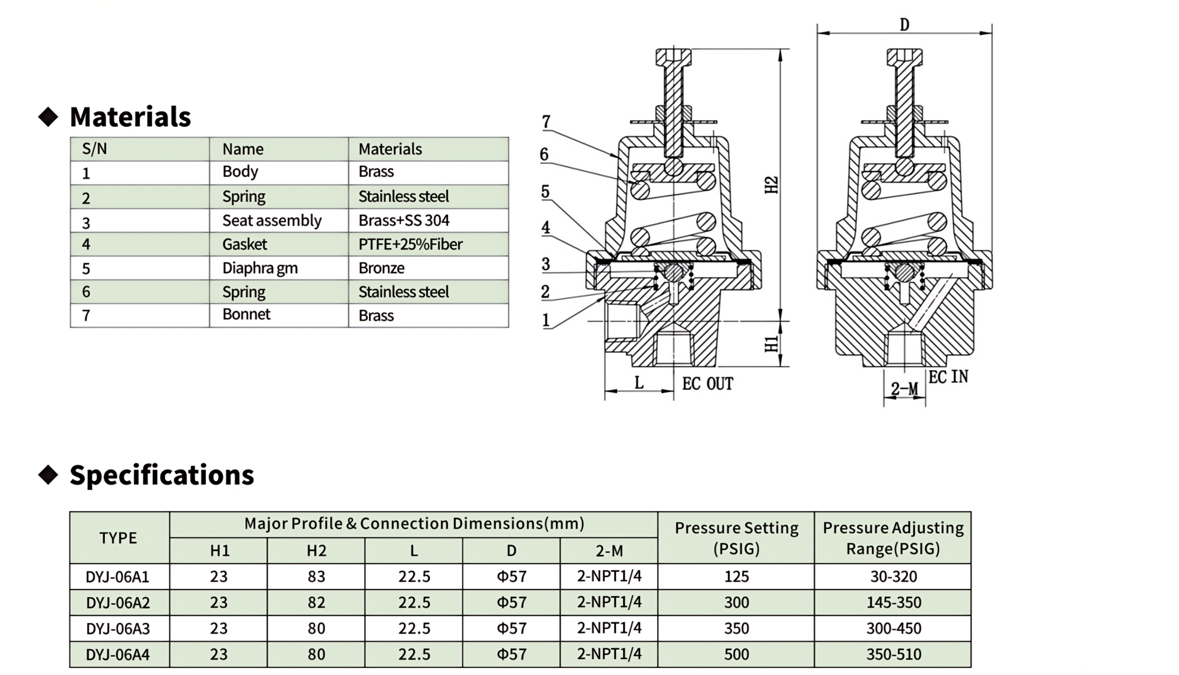
1: Will an economizer and a PB regulator interfere with each other when installed on the same tank?
A: Not only will they not interfere — they collaborate. Their operating bands are non-overlapping: the PB regulator opens when tank pressure is below setpoint and closes at setpoint; the economizer opens when tank pressure is above setpoint and closes at setpoint. Below setpoint: PB open, economizer closed — the system pushes pressure up with full effort. Above setpoint: PB closed, economizer open — the system uses high-pressure gas to serve downstream demand, simultaneously relieving the tank. A tiny overlapping dead band (~±3–5 PSIG hysteresis band) sits between them, the physical consequence of diaphragm mechanical hysteresis — not a design flaw; it actually prevents the two from ping-pong switching at a single pressure point.
2. Why is the DYJ06A's adjusting range so much wider than a comparable PB regulator ?
A: It comes back to ball-and-seat geometry. In a PB regulator's disc-on-flat-seat configuration, the moment the disc lifts, flow area jumps from zero to a cylindrical side area (disc circumference × lift height) — area grows linearly with lift. The ball-and-seat annular-gap area follows π × ball diameter × lift height (small-opening approximation), also linear, but with a larger effective flow diameter — the ball's curved surface offers smoother entry and exit angles for the gas stream, yielding a lower flow contraction coefficient. The result: at equal lift height, the ball-and-seat pair passes more actual flow, so the same spring travel range covers an effectively wider pressure band. Additionally, the ball is lighter than an equivalently sized disc (whether hollow-shell or solid but more compact mass distribution), reducing the diaphragm's driving load — the same vapor pressure pushes through a longer travel.
3. What happens if EC IN and EC OUT are swapped?
A: The economizer is unidirectional — EC IN must connect to the tank vapor space, EC OUT to the downstream line. If reversed, the downstream line pressure acts on the diaphragm instead of tank vapor pressure; the diaphragm reads a downstream pipe reading, not the tank. Two anomalies can result: if downstream pressure exceeds the economizer setpoint → the economizer stays wide open, but flow direction is reversed (gas backflows into the tank); if downstream pressure is below setpoint → the economizer stays shut regardless of how high tank pressure climbs. Field diagnosis is simple: if the tank gauge reads above the economizer setpoint but no gas flows downstream, suspect swapped EC IN/EC OUT.
4. What happens if the tank safety valve's set pressure is identical to the economizer's set pressure?
A: The two become a race — whoever actuates first dictates the outcome. Ideally the economizer opens first (its ball-and-seat pair can establish flow from the micro-open phase), but if setpoints are identical, the most likely real-world outcome is: as tank pressure slowly climbs, the economizer cracks open first and begins bleeding gas; but if downstream consumption is minimal and the economizer's bleed rate cannot halt the pressure rise, the safety valve will lift at the same pressure point.
5. Does a DYJ06A installed on an LNG vehicle cylinder need additional vibration-proofing?
A: The dominant risk in mobile service is not a one-time impact like a speed bump — it is high-frequency low-amplitude vibration from engine idling. This sustained 20–60 Hz micro-vibration affects the economizer through two channels: locknut loosening — similar to DYS15A, but with higher frequency, fatigue loosening accelerates; add a thin jam nut above the locknut or apply a small amount of Loctite 242; ball-seat fretting — if the economizer stays closed for long periods (low tank pressure, valve inactive), the engine's continuous micro-vibration causes nanometer-scale reciprocating sliding between the ball and seat face — this "stationary but trembling" state is an ideal breeding ground for fretting wear. The fix is not a damping pad but ensuring the economizer periodically cycles (after each refueling, tank pressure rebounds and the economizer briefly opens), refreshing the ball-seat contact point.
6.Can the DYJ06A be installed upside down (bonnet facing downward)?
A: Yes — both the diaphragm and ball-seat pair are mechanically force-driven and do not rely on gravity for return. However, one detail matters in inverted installation: condensate drainage. If the EC IN line occasionally draws a trace of condensate mist, in upright orientation the mist settles to the body's lowest point and stays clear of the diaphragm and ball-seat. In inverted orientation the mist settles into the bonnet zone — though the composite gasket (PTFE + 25% fiber) blocks most ingress, for installations with frequent inversion and higher-moisture media, consider adding a miniature gas-liquid separator upstream of EC IN.


 yongy0223@gmail.com
 +86-17693104145
 Lanzhou New Area, Lanzhou City, Gansu Province, on the second floor to the east of New Harbor Road, to the east of Building Materials Road No. 2, to the west of Qilian Mountain Avenue (Jingqi Road)


