| Application Overview
The DYZ15A series is diaphragm-type 3-in-1 combi-pressure regulator designed for DN15-class mid-size cryogenic tanks and process piping. Compared to the compact DYZ06 series, the DYZ15A steps up in bore size (3× NPT 1/2") and flow capacity while maintaining deep integration: pressure build-up, pressure regulation, and economizer priority feed are all merged into a single valve body — no external power, no pilot gas, no separate PB or economizer valve assemblies required.
Design Philosophy: Fit Three Devices into One Brass Block
Cryogenic tank pressure management faces three conflicting demands: falling pressure under draw requires build-up, rising pressure requires cut-off, and adequate pressure calls for vapor-priority feed to avoid wasting liquid. The conventional approach demands three separate devices — a PB valve, a regulator, and an economizer valve — plus six pipe runs and a pile of joints. The DYZ15A collapses all three decisions into a single bronze diaphragm. One side of the diaphragm senses actual tank vapor pressure; the other side is opposed by an adjustable spring. Tank pressure drops → spring pushes through, opens PB. Tank pressure reaches setpoint → vapor pressure pushes back, shuts PB. Tank pressure exceeds setpoint → economizer port opens, feeds vapor directly. The entire cycle is purely mechanical — no circuits, no controllers, nothing that can freeze or lose power.
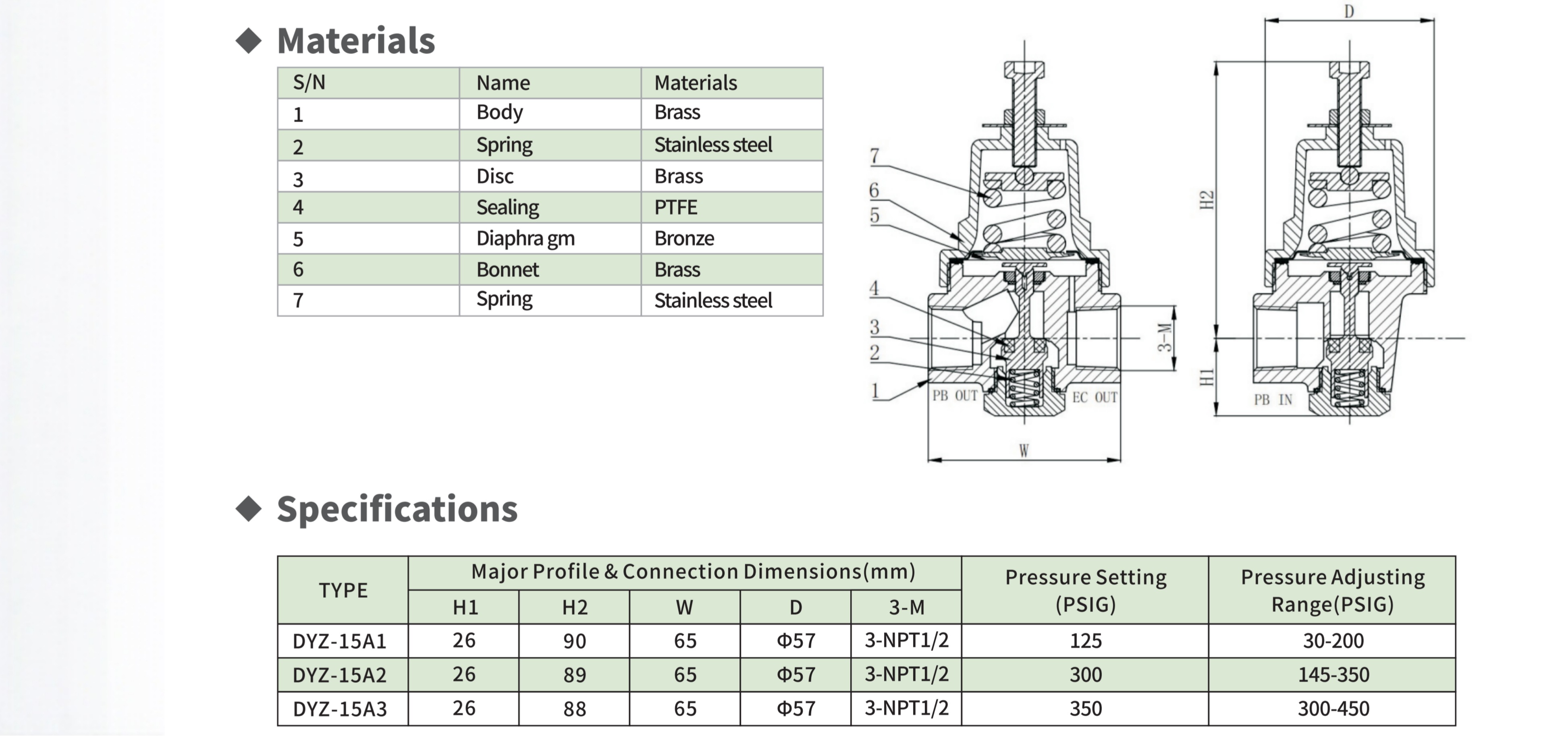
The valve consists of just 7 principal parts: brass body, two stainless steel springs, brass disc, PTFE seat, bronze diaphragm, and brass bonnet. Material selection centers on dimensional stability and tribological compatibility at −196°C: PTFE retains enough pliability for positive shut-off, bronze provides elasticity plus fatigue resistance, and brass/SS pairings avoid cryogenic galling.
Compatible with LNG, LO₂, LN₂, LAr, and all air gases. Every unit ships after CGA G-4.1 LOX-grade degreasing, 100% functional testing, and preset locking to the rated set pressure.
| Working Principle
Core Mechanical Model: Force Balance across a Diaphragm
The DYZ15A is fundamentally a force comparator. The diaphragm decomposes a mechanical control problem into simple addition and subtraction —
Lower side: tank vapor pressure × diaphragm effective area + inlet pressure opening force on the disc
Upper side:adjustable spring preload (continuously set via the top adjustment screw)
The relative strength of these two forces determines the valve's three states. No active control components — no solenoids, no positioners, no interlock logic. The regulator does exactly one thing: compare the two forces, then decide whether the PB circuit is open or closed.
Three-State Automatic Cycle
State 1 — Pressure Build-Up (Tank Pressure Low)
During gas draw, liquid evaporation cannot keep up with the withdrawal rate, and vapor pressure drops below the setpoint. The spring force on the upper side of the diaphragm exceeds the gas force on the lower side, pushing the diaphragm and stem downward. The disc lifts off the PTFE seat, opening the PB IN→PB OUT passage. Liquid cryogen from the tank bottom flows through PB IN into the external build-up coil, vaporizes and expands at ambient temperature, and returns as gas through PB OUT to the tank's vapor space, replenishing pressure. The EC OUT port may also see some flow during this phase, but it is downstream-restricted and does not interfere with the priority build-up function.
State 2 — Equilibrium Cut-Off (Pressure at Setpoint)
As pressure build-up continues, tank vapor pressure gradually climbs to the setpoint. Forces on both sides of the diaphragm enter the equilibrium zone. The diaphragm and stem begin to retract, bringing the disc toward the PTFE seat. At the exact moment tank pressure equals the setpoint, the disc fully seats — the PTFE soft seal undergoes micro-deformation at cryogenic temperature to conform to the seat, achieving a positive shut-off of the PB circuit. The tank now enters a "pressure-locked" state, neither building nor venting.
State 3 — Economizer Priority (Pressure Above Setpoint)
Immediately after tank filling, or when elevated ambient temperatures increase natural boil-off, tank pressure may briefly exceed the setpoint. The diaphragm is pushed to its upper limit, the disc remains seated (PB circuit stays closed), and the EC OUT economizer port becomes the primary gas supply path — drawing high-pressure vapor directly from the tank's vapor space to feed downstream equipment. The critical advantage: this path extracts gas that already exists as vapor, avoiding the need to first evaporate liquid — eliminating unnecessary liquid consumption and the extra cooling load that comes with it.
Closed-Loop Cycling
This three-state cycle is a purely physical closed loop. No timers, no threshold detectors, no digital logic — the diaphragm's mechanical movement is itself the controller. Build-up → pressure exceeds setpoint → mechanical cut-off → gas withdrawal depletes pressure → pressure drops below setpoint → spring re-opens the disc → build-up restarts. Cycle frequency is determined entirely by the natural rhythm of gas consumption and the tank's thermal equilibrium.

|
Factory Shoot
1: What is the essential difference between the DYZ15A and DYZ06 series? How should I choose?
A: The core difference lies in the diameter and flow rate. DYZ15A with NPT 1/ 2" interface, DYZ06 series (A / C) with NPT 1 / 4". This means that the flow capacity of DYZ15a is significantly higher, making it suitable for scenarios that require a larger gas supply or a faster pressure boost response.
Selection experience rule:
Small Dewar bottle (≤240L), single-handle welding gun, laboratory gas pipeline → DYZ05 is sufficient and more cost-effective
Medium storage tank (Mini-Bulk 500L~ 3000L), multi-way gas, or need larger flow rate of ECO export → select DYZ15
In case of uncertainty: If you are currently using NPT 1/ 2 on your pipeline "Connector → DYZ14A;NPT 1/4 " → DYZ06
The installation idea and operation method of the two are exactly the same, which can be understood as the derivative model of the same design on different diameters.
2. What does "adjusting range" mean? What is the relationship between set pressure and adjusting range?
A: Take DYZ-15A2 as an example: the factory set pressure is 300 PSIG (locked), but if on-site fine-tuning is needed, the screw can be adjusted anywhere within the 145–350 PSIG range — that is the "adjusting range". Adjustment outside this range is ineffective: spring stiffness makes sealing unreliable below 145 PSIG, while the diaphragm reaches its stroke limit above 350 PSIG with no further effect on pressure.
Adjustment procedure: loosen the top locknut → use a wrench to rotate the adjusting screw (clockwise to raise, counterclockwise to lower) → observe the tank pressure gauge → relock at the target. Do not adjust the factory preset on first commissioning — the default is the optimal working point for that sub-model.
3. Are the diaphragm and PTFE seat wear items, and how often do they need replacement?
A: The bronze diaphragm is a long-life part under normal operation, with an expected service life exceeding 5 years. Its common failure mode is not fatigue fracture but gradual loss of springback elasticity from repeated large-deflection cycling — the diaphragm's restoring force degrades year over year, eventually causing the setpoint to drift downward (pressure will not climb to spec). Diagnostic rule: if the locknut is intact, the screw is undamaged, yet tank pressure sits noticeably below setpoint, the diaphragm and/or spring is most likely degraded, and a service kit replacement is needed.
The PTFE seat has a shorter service life (approximately 2–3 years or 500–1000 PB cycles), making it the more frequently replaced wear item. Both components are included in our service kit.
4.Can this valve be used in liquid oxygen service, and what handling is required?
A: LOX service is supported, with one critical prerequisite: the valve is factory-degreased per CGA G-4.1, and must not contact any oil or grease after the bag is opened. Installers must wear clean gloves, and any PTFE tape used must be oxygen-grade (grease-free). If at any moment you are unsure of glove cleanliness, rewash rather than proceed — oil residue inside an oxygen line at high pressure can auto-ignite. The failure mode is not "valve breaks" — it is "tank explodes".
5. Can the DYZ15A be installed horizontally or upside-down?
A: Not recommended, and there is no practical reason to do so. The force-balance calculation in a diaphragm-type self-operated regulator assumes vertical installation — the diaphragm's own weight is part of the balance equation. Horizontal or inverted mounting introduces gravity bias, causing systematic setpoint error (typically 5–10 PSIG low) that cannot be compensated via the adjustment screw. Additionally, inverted mounting traps condensate inside the bonnet's spring chamber, leading to long-term spring corrosion.
Correct installation posture: valve body vertical, adjustment screw on top, three ports extending horizontally. This matches the standard mounting orientation on most tank tops or side walls, requiring no extra bracket.


 yongy0223@gmail.com
 +86-17693104145
 Lanzhou New Area, Lanzhou City, Gansu Province, on the second floor to the east of New Harbor Road, to the east of Building Materials Road No. 2, to the west of Qilian Mountain Avenue (Jingqi Road)