


Views: 0 Author: Site Editor Publish Time: 2026-07-08 Origin: Site


Managing pressure in extreme low-temperature environments down to -196°C leaves zero margin for error. System engineers must balance precise flow control with stringent safety, material contraction, and spatial constraints. Traditional pressure management on a cryogenic tank requires a complex, multi-valve assembly. This setup typically involves separate pressure build-up regulators, economisers, thermal relief valves, and associated piping. This fragmented approach multiplies potential leak paths, increases installation labor, complicates maintenance, and elevates the risk of stem packing freeze-ups. Deciding between a traditional multi-valve setup and a unified cryogenic combi pressure regulator requires a strict technical evaluation. Engineers must assess system footprint, long-term reliability, and testing compliance to make an informed selection that ensures operational stability.
Consolidated Functionality: A cryogenic combi pressure regulator integrates both pressure build-up and economiser functions into a single unit, significantly reducing the required piping footprint on a cryogenic tank.
Risk Reduction: By replacing multiple standard cryogenic valves with one combi unit, engineers eliminate redundant joints and connections, directly reducing potential leak paths and points of fugitive emission failure.
Advanced Materials and Design: Cryogenic-pressure regulators must feature extended bonnets/columns to protect gland packing from freezing, a critical design element that prevents operational failures common in substandard valves.
Testing & Quality Assurance: Implementing a combi regulator simplifies the compliance pathway, as testing a single integrated valve for cryogenic seat and shell tightness is significantly faster and more reliable than testing an entire multi-valve manifold.
Retrofit Viability: Transitioning existing systems to combi regulators requires careful assessment of existing pipework geometry, thermal contraction allowances, and flow capacity (Cv) requirements.
The standard approach utilizes separate cryogenic valves for pressure build-up and economiser functions. This configuration demands extensive interconnecting piping, isolation valves, and thermal expansion relief devices. The spatial footprint required for this manifold is substantial, often complicating installations in tight spaces. Multi-component systems remain highly vulnerable to thermal contraction stresses. Extreme temperature fluctuations cause independent components to contract at different rates, stressing welded and threaded joints. Furthermore, this setup introduces the severe risk of cryogenic liquid trapping between isolation valves, which can lead to catastrophic pressure ruptures if thermal relief devices fail.
When evaluating legacy systems, engineers frequently encounter sprawling manifolds that require constant monitoring. Each threaded connection or brazed joint represents a potential failure point. Field technicians spend excessive hours leak-testing these complex assemblies during initial commissioning and routine maintenance turnarounds. The sheer volume of components also increases the likelihood of mismatched materials, leading to galvanic corrosion or uneven thermal expansion rates across the manifold.
The combi design merges pressure build-up and economiser circuits into a single forged or cast bronze or stainless steel body. This unified architecture streamlines fluid flow and reduces the physical footprint. The extended bonnet, or gas column, plays a critical role in this design. It keeps the stem packing close to ambient temperature, preventing ice formation and subsequent packing failure. Internally, actuation and pressure-sensing mechanisms utilize precision diaphragms or bellows. These allow dual-functionality without cross-interference or pressure hunting. Engineering tolerances are exceptionally tight to maintain seat sealing across extreme temperature gradients, ensuring reliable operation from ambient conditions down to -196°C.
To understand the mechanical superiority of the combi architecture, consider the internal flow paths. Instead of routing fluid through external piping to reach the economiser, the combi valve utilizes internal porting. This internal routing minimizes pressure drops and accelerates response times to system fluctuations. The integration of these functions requires advanced machining capabilities to ensure that the internal galleries are free of burrs or restrictions that could cause turbulent flow or cavitation.
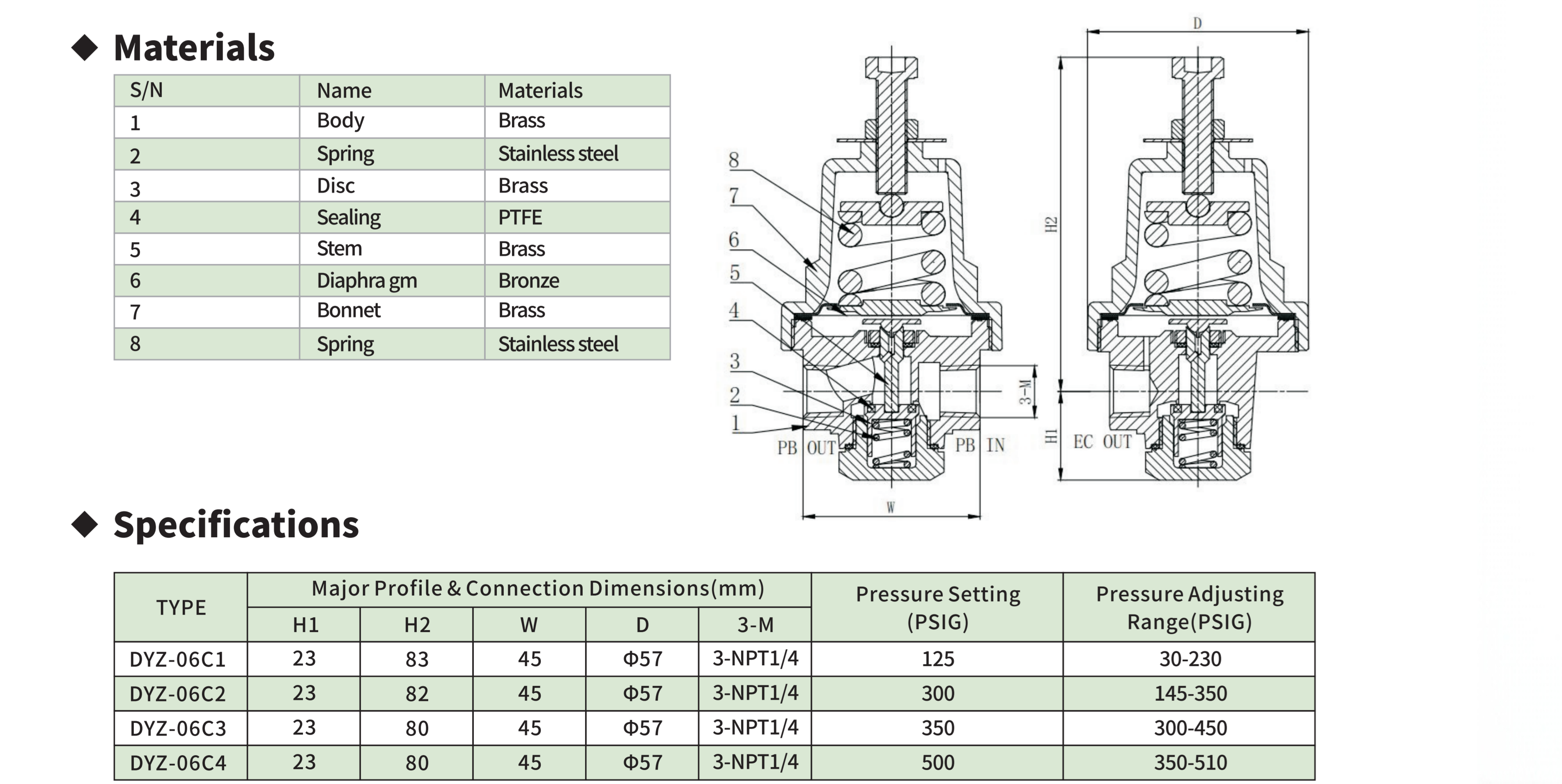
Moving from standard setups to a unified combi unit drastically reduces brazed, welded, and threaded connections. Fewer joints directly translate to enhanced vacuum insulation integrity, particularly in jacketed tanks where a loss of vacuum degrades thermal performance. Fugitive emission mitigation also improves significantly with a consolidated valve body. Rigorous testing standards govern these assemblies. Helium mass spectrometer leak testing and cryogenic shell and seat testing ensure that the single unit maintains absolute integrity under operational stresses.
System Type | Average Connection Points | Leak Potential | Maintenance Frequency |
|---|---|---|---|
Traditional Multi-Valve | 12 - 18 | High | Quarterly |
Combi Pressure Regulator | 4 - 6 | Low | Annually |
A cryogenic-pressure regulator manages boil-off gas highly effectively compared to a standalone, discrete economiser valve. The integrated nature allows for immediate internal routing of excess head pressure, prioritizing gas phase withdrawal to maintain optimal tank conditions. Response times to sudden pressure fluctuations are rapid. This prevents the unnecessary venting of valuable cryogenic gas to the atmosphere, directly improving the overall thermal efficiency of the storage system.
Comparing the flow coefficient (Cv) values and pressure drop characteristics is essential. Combi regulators are engineered to match or exceed the flow stability of discrete valves. Performance remains consistent under varying load conditions, from high-draw liquid withdrawal scenarios to long-term static storage. Proper sizing requires a detailed analysis of the maximum anticipated flow rates and the specific gravity of the cryogenic fluid being handled.
Combi units offer distinct spatial advantages for micro-bulk tanks, ISO containers, transport trailers, and densely packed manifold cabinets. Consolidating functions reduces the need for complex pipe bending, custom supporting brackets, and extensive insulation jacketing. This streamlined footprint allows engineers to design more compact and efficient storage solutions.
Isolate the main liquid and gas withdrawal lines.
Depressurize the system completely using approved venting procedures.
Remove the existing multi-valve manifold, taking care to cap open lines immediately to prevent moisture ingress.
Align the new combi regulator with the existing pipe centers, utilizing transition fittings if necessary.
Torque all connections to the manufacturer's specified values.
Perform a localized helium leak test before returning the system to service.
Cryogenic systems present extreme risks, notably cryogenic burns to operators handling cold valve components. The extended bonnet design and integrated insulation barriers on combi valves minimize external cold spots during active pressure building cycles. This keeps operational interfaces closer to safe ambient temperatures, protecting personnel during routine adjustments.
Servicing a single combi cartridge or diaphragm is fundamentally simpler than troubleshooting multiple discrete setups. Many modern combi designs support top-entry servicing. This allows technicians to perform in-line maintenance using standard repair kits without removing the valve body from the pipework, drastically cutting system downtime.
Cryogenic valves must adhere to strict regulatory frameworks, including ISO 21011, EN 1626, and ASME B31.3. Regional directives like PED and TPED also dictate design and safety parameters. Testing protocols for cryogenic service are unforgiving. They mandate ambient shell and seat tests, cryogenic temperature proof tests, and rigorous cycle testing under extreme cold to validate mechanical endurance.
A factory-tested combi regulator undergoes comprehensive quality assurance as a complete system. This contrasts sharply with a field-assembled multi-valve manifold, where individual components might pass factory tests, but the assembled system remains unverified until commissioning. Factory-set combi regulators reduce installation commission times and minimize the risk of field inspection failures.
Purchasing one combi regulator often presents a different initial capital outlay compared to buying a separate pressure build-up valve, economiser, and associated fittings. However, the true value emerges during installation. Traditional multi-valve installations demand extensive skilled labor, including specialized welding, brazing, and non-destructive testing (NDT). The combi unit eliminates much of this labor, offering substantial installation savings that offset initial component investments.
Beyond the immediate installation phase, the reduction in required spare parts inventory provides ongoing operational benefits. Facilities no longer need to stock multiple rebuild kits for different valve types and sizes. A single standardized repair kit for the combi unit simplifies procurement and ensures that maintenance teams always have the necessary components on hand during emergency repairs.
Replacing an existing multi-valve setup with a combi regulator presents specific engineering challenges. Mismatched pipe centers, differing thread standards, and altered thermal expansion dynamics must be addressed. Engineers can mitigate these risks by utilizing custom transition fittings. Scheduling retrofits during major tank refurbishments or vacuum re-vacuuming cycles ensures that piping modifications are executed safely and efficiently.
Relying on a proprietary combi design carries the risk of vendor lock-in, compared to universally available standard valves. To mitigate this, facilities should evaluate vendor lead times and technical support availability. Prioritizing manufacturers that standardize internal cartridge components across their product lines ensures easier access to spare parts and simplifies long-term maintenance strategies.
While standard configurations offer modularity for highly customized setups, the combi regulator provides superior value in applications where space, leak prevention, thermal efficiency, and installation speed are paramount. Choose standard multi-valve setups for highly customized, ultra-high-flow legacy systems where retrofitting is structurally prohibitive. Specify combi regulators for new OEM tank builds, transport applications, micro-bulk installations, and systems requiring strict minimization of leak paths.
Calculate current assembly and installation labor costs for multi-valve setups.
Review the spatial constraints and piping geometry of your next tank build project.
Request technical datasheets and Cv flow curves from reputable combi regulator manufacturers.
Audit your existing spare parts inventory to identify consolidation opportunities.
A: It combines the pressure build-up regulator and the economiser valve into a single unit to maintain optimal operating pressure inside a cryogenic tank while minimizing gas venting.
A: Standard valves lack the cryogenic-grade materials needed to withstand extreme cold without becoming brittle, and they do not have extended bonnets to protect stem packing from freezing and leaking.
A: Yes, but it requires verifying the existing pipework dimensions, thermal contraction allowances, flow capacity requirements, and connection types. Retrofitting often requires minor piping modifications.
A: By integrating two distinct valve functions into one body, it eliminates the need for the intermediate piping, elbows, and threaded or welded joints required in a traditional setup.
A: Generally, no. While internally more complex, many modern combi regulators feature top-entry designs or replaceable cartridges, allowing for in-line maintenance without removing the entire unit from the piping.
A: They must comply with stringent industrial standards such as ASME B31.3, ISO 21011, EN 1626, and regional directives like PED or TPED, ensuring they can withstand extreme thermal cycling and high pressures without failure.

 yongy0223@gmail.com
 +86-17693104145
 Lanzhou New Area, Lanzhou City, Gansu Province, on the second floor to the east of New Harbor Road, to the east of Building Materials Road No. 2, to the west of Qilian Mountain Avenue (Jingqi Road)


