


Views: 0 Author: Site Editor Publish Time: 2026-07-29 Origin: Site


Pressure management in cryogenic fluid systems is a critical operational requirement. When pressure regulation is improperly handled, facilities face excessive boil-off gas (BOG) losses, unplanned system downtime, or catastrophic over-pressurization events. Integrating dual-function components presents a specific mechanical challenge. A misaligned installation of a combined pressure build-up and economizer valve, commonly known as a cryogenic combi pressure regulator, can result in internal ice formation, erratic flow control, and compromised safety protocols across the entire storage infrastructure.
This guide serves as a comprehensive, step-by-step technical framework for evaluating, preparing, and executing the installation of these complex regulators. By following these structured methodologies, technicians can ensure system integrity, optimize flow dynamics, and maintain strict regulatory compliance throughout the lifecycle of the equipment.
Orientation is Manufacturer-Specific: Installation orientation is strictly dictated by the manufacturer's engineering design (e.g., Parker Bestobell Cryoreg requires the pressure setting screw downwards to prevent ice formation, whereas the Cash Valve Type E-55 requires a horizontal position with the spring chamber upright).
System Integration Requires Auxiliary Protection: Integrating a cryogenic-pressure regulator into a cryogenic tank system necessitates properly placed thermal relief valves (TRVs), especially between the economizer port (Port C) and any downstream isolating cryogenic valves.
Cleanliness is Non-Negotiable: All components, tools, and connected piping must be strictly cleaned and certified for oxygen service (even if used with inert gases) to prevent combustion risks and seat contamination.
Calibration Dictates Efficiency: Proper sequential calibration of the pressure build-up and economizer functions prevents erratic valve cycling, significantly reducing product loss and stabilizing operating pressure.
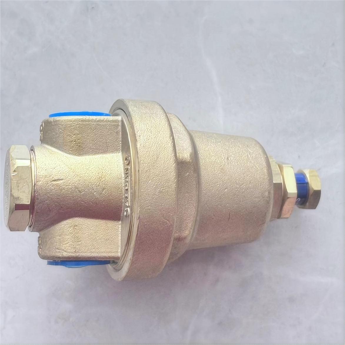
A successful installation must seamlessly manage both the pressure building circuit and the economizer circuit without cross-interference or thermal shock. The pressure building circuit handles liquid withdrawal and vaporization to maintain adequate head pressure. Conversely, the economizer circuit vents excess vapor head pressure into the withdrawal line to prevent unnecessary atmospheric venting. Establishing this operational baseline is the primary success criteria for any deployment. When you install these units, you are essentially balancing two opposing forces within the same brass or stainless steel housing. The internal bellows or diaphragms must react instantly to pressure drops caused by liquid withdrawal, opening the build-up seat to allow vaporized gas back into the tank. Simultaneously, if the tank sits idle and ambient heat leak causes the internal pressure to rise above the setpoint, the economizer seat must open to prioritize drawing off the head gas rather than liquid.
Traditional systems often rely on standalone pressure build-up regulators paired with separate economizer valves. The unified combi approach consolidates these functions into a single body. This integration directly reduces the total number of required cryogenic valves, minimizes potential leak paths, and significantly decreases the overall piping footprint on the vessel. Understanding how these features translate to operational outcomes is essential for proper system design and implementation. Every threaded connection you eliminate by using a combination valve removes a potential point of failure where thermal cycling could cause a leak. Furthermore, the reduced mass of a single valve compared to two separate valves means less heat is transferred into the cryogenic fluid during the initial cool-down phase, improving overall system efficiency.
To fully grasp the mechanical advantage, consider the internal flow paths. In a standard setup, gas from the pressure building vaporizer enters the inlet port and is directed into the tank's vapor space. When the economizer function activates, the internal mechanism shifts, closing off the vaporizer feed and opening a path from the tank's vapor space directly into the liquid withdrawal line downstream of the main liquid valve. This clever routing ensures that the system consumes the excess pressure before it reaches the safety relief valves, saving valuable product and preventing the loud, disruptive venting that often plagues poorly regulated tanks.
Before initiating any physical work, a thorough evaluation of system compatibility is required. You must verify that the maximum allowable working pressure (MAWP) of the vessel aligns perfectly with the regulator’s maximum inlet pressure rating. Confirm the flow capacity requirements for both liquid and gas phases to avoid sizing bottlenecks during peak withdrawal rates. Additionally, assess material compatibility. Most regulators are constructed from bronze, brass, or stainless steel, which must be verified against the specific cryogen being handled. For example, while brass is excellent for liquid oxygen and nitrogen, certain specialized applications might demand stainless steel for enhanced durability or specific chemical compatibility.
Cross-referencing the regulator's port scheme with the physical piping layout of the cryogenic tank is a mandatory step. You must locate and verify all physical ports on the regulator body to ensure proper routing. Misidentifying the economizer port and connecting it to the pressure building line will result in immediate system failure and potential over-pressurization.
Port Designation | Standard Connection Point | Primary Function |
|---|---|---|
Inlet Port | Pressure builder vaporizer output | Receives vaporized gas to build tank pressure. |
Outlet Port | Vapor space of the tank | Directs gas into the tank to maintain head pressure. |
Port C (Economizer) | Economizer line / Liquid withdrawal line | Routes excess head pressure into the process line. |
Ensure the selected regulator meets regional and industry standards, including the ASME Boiler and Pressure Vessel Code and PED requirements. The unit must be cleaned for oxygen service per CGA G-4.1 specifications. Finally, evaluate the physical clearance for the installation. There must be adequate space for wrench access, downstream test ports, and future in-line maintenance. You do not want to install a valve in a location where you cannot easily reach the adjustment screw or where a technician would have to contort themselves to perform a simple leak check.
Site preparation involves a systematic approach to the physical workspace. Follow these numbered steps to ensure the area is ready for installation:
Clear the immediate area of any combustible materials, especially if working with oxygen systems.
Erect physical barriers or warning signs to prevent unauthorized personnel from entering the work zone during depressurization.
Verify that adequate ventilation is present to disperse any vented nitrogen or argon gas, preventing asphyxiation risks.
Stage all required tools and replacement parts on a clean, lint-free surface to maintain oxygen-clean standards.
Inspect the existing piping for signs of severe corrosion, physical damage, or previous improper modifications that need correction before installing the new valve.
Working with extremely low temperatures requires specialized safety gear. Technicians must wear cryogenic gloves, full face shields, safety glasses, and appropriate non-porous protective clothing to prevent severe frostbite and cold burns. Safety is the absolute priority during any system modification. Cryogenic liquids expand rapidly when exposed to ambient temperatures, and a small splash can cause significant injury. Always ensure your gloves are loose-fitting so they can be quickly thrown off if liquid spills inside them.
The correct tooling and diagnostic equipment prevent mechanical damage during assembly. Required items include:
Non-sparking wrenches to prevent ignition risks in oxygen-enriched environments.
Calibrated torque wrenches to ensure precise connection tightening.
Calibrated pressure gauges for accurate inlet and outlet pressure monitoring during testing.
Leak detection fluids specifically approved for low temperatures and oxygen service.
Lint-free cloths and approved oxygen-compatible cleaning solvents for wiping down mating surfaces.
A dedicated lockout/tagout (LOTO) kit with multiple padlocks and highly visible tags.
Thread sealants must be chosen with extreme care. Identify and use only approved PTFE tapes or oxygen-compatible liquid sealants. Using standard hydrocarbon-based sealants in oxygen-enriched environments poses an absolute combustion risk and must be strictly avoided. When selecting PTFE tape, ensure it is the high-density, oxygen-approved variety, often color-coded green or clearly marked for such service. Standard white plumbing tape is often manufactured with hydrocarbon-based lubricants that can ignite under pressure in an oxygen system.
Isolating the storage vessel and fully depressurizing the specific piping section is an absolute necessity. Begin by safely venting any trapped liquid and gas away from personnel and enclosed spaces. Execute strict lockout/tagout (LOTO) procedures for all upstream and downstream valves, including liquid withdrawal and vapor return lines. Never rely on a single closed valve if a double block and bleed arrangement is possible. The immense expansion ratio of cryogenic liquids means that even a tiny amount of liquid leaking past an isolation valve can rapidly pressurize the line you are working on.
Once isolated, purge the lines with dry nitrogen gas. This eliminates moisture and residual process gases that could freeze upon introduction of the cryogen, causing internal blockages or seat damage. Connect a regulated nitrogen source to a purge port and sweep the lines thoroughly. Verify the effectiveness of the purge by checking the dew point of the exhaust gas if possible, ensuring it is well below freezing to guarantee all ambient moisture has been expelled.
Addressing conflicting orientation requirements across different manufacturers is crucial to prevent rapid icing and mechanical failure. Moisture management physics dictate how these valves operate in ambient conditions. If installed incorrectly, ambient condensation can pool in the spring housing, freeze, and seize the internal regulating diaphragm or bellows. This freezing action locks the valve in its current position, rendering it completely incapable of regulating pressure.
Review the specific manufacturer instructions carefully. For instance, certain models must be installed with the pressure setting screw pointing downwards to prevent moisture ingress. Other models require installation in a horizontal pipe run with the spring chamber upright. Never assume orientation based on previous installations of different brands. The internal weep holes designed to drain condensation only function if gravity is working in the direction the engineers intended.
When applying PTFE tape, start at least one thread back from the lead edge. This prevents loose tape shreds from entering the valve body and damaging the soft seats. Wrap the tape tightly in the direction of the threads, usually requiring three to four full wraps for a secure seal. Map the port alignment carefully: connect the inlet to the pressure builder vaporizer output, the outlet to the vapor space, and the economizer port to the designated economizer line.
Follow exact torque specifications for tightening threaded or flanged connections. Over-tightening can distort the valve body or damage internal seats, while under-tightening leads to dangerous thermal leaks during operation. Use two wrenches when making up threaded connections: one to hold the valve body steady and the other to turn the fitting. This prevents transferring rotational stress into the internal components of the regulator.
Integrating a cryogenic-pressure regulator requires auxiliary safety components. You must install a dedicated thermal relief valve (TRV) anywhere liquid can be trapped between two closed valves. If an isolating valve is fitted in the economizer line, a separate TRV must be installed between the economizer port and that isolating valve. Without this TRV, trapped liquid will absorb ambient heat, expand, and rupture the piping or the regulator body.
Mandate the installation of a fine-mesh, low-temperature-rated strainer upstream of the regulator. This protects the internal seats from scale or particulate damage. Integrate test connections and keyed hose bibs for safe purging, sampling, and pressure checking during system commissioning. These small additions make future maintenance significantly safer and more efficient.
Calibrating the unit involves balancing the need to maintain adequate head pressure for liquid withdrawal against the goal of minimizing BOG venting losses. This requires a sequential adjustment process to prevent erratic cycling. If the build-up and economizer settings overlap, the valve will constantly fight itself, rapidly opening and closing, which destroys the internal seats and wastes massive amounts of gas.
First, isolate the economizer circuit. Adjust the pressure build-up setting screw until the desired minimum vessel operating pressure is achieved. Turn the screw clockwise to increase the pressure setting and counter-clockwise to decrease it. Make small adjustments and allow the system to stabilize for several minutes between turns. The thermal mass of the system means pressure changes are not always instantaneous.
Next, engage the economizer circuit. Calibrate the setpoint to route excess vapor back to the process lines. This is typically designed to actuate at a set differential of 10-15 PSI above the build-up pressure. Utilize calibrated pressure gauges to monitor system response during the initial liquid introduction. Validate the baseline curves against the manufacturer's technical specifications to ensure optimal performance. Watch the gauges closely during a simulated liquid withdrawal to ensure the pressure drops slightly, the build-up circuit engages, and the pressure recovers smoothly without overshooting into the economizer range.
Even with careful installation, operational risks can arise. Ice formation in the spring chamber or stem binding is a frequent issue. To mitigate this, verify the correct installation orientation and ensure that all environmental weep holes are entirely unobstructed. Sometimes, technicians accidentally paint over these weep holes or cover them with insulation, trapping moisture inside the housing.
If the system experiences continuous venting or fails to build pressure, check for particulate debris on the main valve seat. Even a microscopic piece of PTFE tape or pipe scale can hold the seat open. Verify that the economizer and build-up settings are not overlapping or set in reverse. Thermal leakage at threaded joints during cool-down is another common risk. Perform a step-down cool-down process and re-torque connections only after the system has fully stabilized at operating temperatures to account for physical thermal contraction. Brass and stainless steel contract at different rates, so a joint that is tight at room temperature may weep when chilled to -320°F.
Establishing a baseline preventive maintenance schedule ensures long-term reliability. This schedule should include bi-annual leak checks and annual set-point drift monitoring. Regular inspections prevent minor issues from escalating into major system failures. Document every pressure adjustment and leak test in a dedicated equipment log to track the performance degradation over time.
Evaluate the advantages of inline repairability. Regulators that feature cartridge-based or top-entry designs allow for quick diaphragm and seat replacement. This eliminates the need for desoldering or unthreading the entire valve body from the piping matrix, significantly reducing maintenance downtime and labor requirements. When a rebuild is necessary, always use the manufacturer's certified rebuild kits, ensuring all replacement soft goods are rated for the specific cryogenic temperatures and oxygen service requirements of your system.
Installing these specialized regulators is a high-precision task. Strict adherence to orientation requirements, absolute cleanliness, and methodical calibration directly dictate system safety, operational efficiency, and component lifespan. Proper execution prevents product loss and protects the surrounding infrastructure.
Verify all flow requirements and port mappings against your existing piping layout before purchasing components.
Consult specific product installation, operation, and maintenance manuals to confirm exact orientation constraints.
Engage a qualified systems engineer to review the final assembly and safety relief valve placements.
Establish a routine maintenance log to track set-point drift and schedule preventative seat replacements.
A: Orientation is strictly manufacturer-dependent. Some models require the adjustment screw to face downwards to prevent internal icing, whereas others must be installed horizontally with the spring chamber upright. Always consult the specific unit's installation manual.
A: Yes. If an isolating valve is fitted in the economizer line, you must install a separate TRV between the economizer port and the isolating valve to prevent over-pressurization from trapped expanding liquid.
A: Components cleaned for oxygen service are free from hydrocarbons and particulates. This strict cleanliness prevents seat contamination, ensures tight shut-off, and maintains safety standards if the equipment is later repurposed.
A: Perform a gradual step-down cool-down process. Re-torque the threaded connections only after the piping has fully stabilized at cryogenic operating temperatures to account for natural thermal contraction.
A: Continuous venting usually indicates particulate debris on the main valve seat preventing closure, or that the economizer and pressure build-up settings are overlapping or set in reverse.

 yongy0223@gmail.com
 +86-17693104145
 Lanzhou New Area, Lanzhou City, Gansu Province, on the second floor to the east of New Harbor Road, to the east of Building Materials Road No. 2, to the west of Qilian Mountain Avenue (Jingqi Road)


