

 |


loading


DYJ25A
SLDW
| Size: | |
|---|---|
| Availability: | |
| Quantity: | |
| Product Overview
The DYJ15B is the brass-body variant in the DYJ pressure-reducing regulator family—a deliberate material trade-off that optimizes for acquisition cost and installation compactness while maintaining the full 580 PSIG pressure rating and four-band progressive range coverage of its stainless steel sibling, the DYJ15A. The "B" suffix here carries the same logic as "B" in the DGF15/25B basket strainer and DYS15B heavy-duty pressure-building regulator: a departure from the base material specification, driven by a specific application or manufacturing rationale.
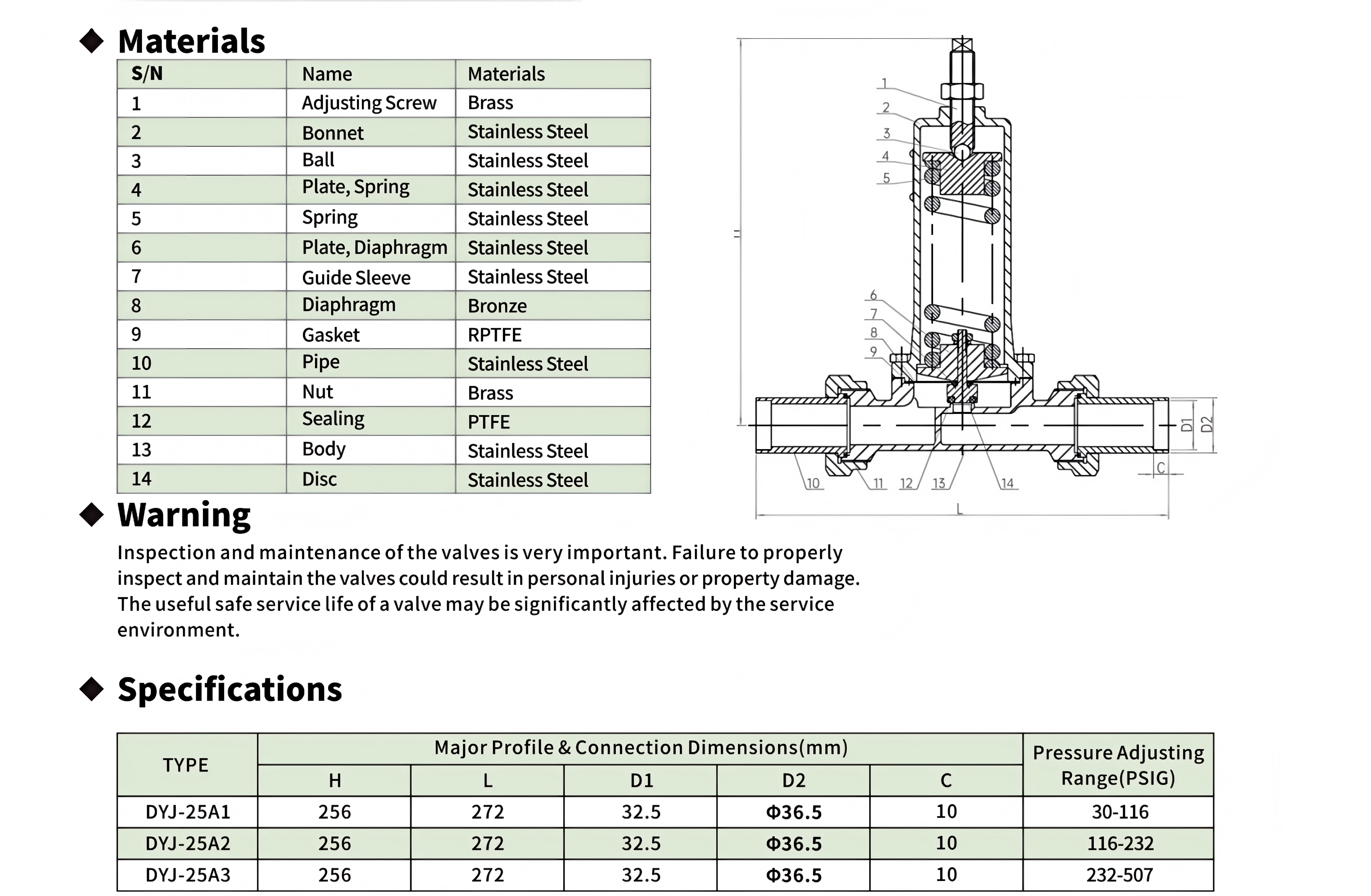
The DYJ25A is the DN25 large-bore member of the DYJ pressure-reducing regulator family—a 14-component ball-seat-guide machine that shares its internal architecture with the DYS25A back-pressure economizer but configures it for downstream-sensing pressure reduction rather than upstream-sensing pressure relief. At H = 256 mm long and L = 272 mm overall, it is physically the largest regulator in the entire DJ series product line, exceeding even the DYS20A (255 mm) by a millimeter and dwarfing the compact DYJ15A (125 mm) and DYJ15B (108 mm). This is not a scaled-up version of the DYJ15 family—it is an entirely different valve genus built around a fundamentally different internal mechanism.
The 14-component count is the immediate indicator of architectural divergence. Where the DYJ15A and DYJ15B both use a simplified 7-component direct-acting architecture (spring → diaphragm → plate → PTFE seal, with the seal element directly bearing on the seat orifice), the DYJ25A interposes three additional precision elements between the spring force and the sealing interface: a stainless steel ball (component 3), a guide sleeve (component 7), and a stainless steel disc (component 14). The ball is not a check element—it functions as a spherical thrust bearing that decouples the spring's axial force vector from any off-axis misalignment that the diaphragm or adjusting screw might introduce. The guide sleeve constrains the disc to linear motion along the flow axis, preventing the disc edge from cantilevering into the bore wall and creating an uneven circumferential seal loading pattern. The disc itself is a full-diameter stainless steel poppet with a PTFE face seal (component 12) that mates against a machined seat in the stainless steel body (component 13). This tri-element force train—ball → spring plate → guide sleeve → disc—adds seven components over the DYJ15's architecture but eliminates the single largest source of premature seat wear in direct-acting cryogenic regulators: eccentric disc loading due to diaphragm hysteresis.
The swivel nut connection (components 10 and 11: pipe and brass nut) is the second major departure. Unlike the NPT-1/2 threaded body ports on the DYJ15 family, the DYJ25A uses union-style swivel nuts on both inlet and outlet. This has three consequences for installation and maintenance. First, the valve body does not need to rotate during installation—the 256 mm tall, 14-component stainless steel assembly is heavy enough that rotating it against pipe threads would require a pipe wrench on the body (risking distortion of the precision-bored guide sleeve bore) or a custom spanner on the bonnet hex (which is not designed for installation torque). The swivel nut eliminates this problem entirely: the body stays stationary while only the nut rotates, and the RPTFE gasket (component 9) forms the pressure seal between the pipe flange face and the body counterbore. Second, the swivel nut connection allows the valve to be removed for service without disturbing the upstream and downstream piping—a significant advantage in welded or hard-plumbed cryogenic installations where cutting and re-welding pipe would require a full system purge, warm-up, and re-commissioning sequence. Third, the D1 = 32.5 mm flow bore through the swivel nut is substantially larger than the NPT-1/2 equivalent flow diameter (~14 mm for schedule 40 pipe), providing roughly 5.4× the flow area. This is the primary reason the DYJ25A exists as a product: it addresses flow rates where a single DYJ15A would be operating at or beyond its choked flow limit, causing cavitation-like pressure oscillations in the downstream gas header.
The three-range progressive architecture (A1: 30–116, A2: 116–232, A3: 232–507 PSIG) is also worth examining against the DYJ15A/B's four-range scheme. The DYJ25A consolidates what would be the A3 and A4 ranges of the DYJ15A (290–435 and 435–507) into a single A3 range (232–507 PSIG). This is not an arbitrary simplification—it is a deliberate consequence of the larger diaphragm area in the DN25 body. The DYJ25A's bronze diaphragm (component 8) has a significantly larger effective area than the DYJ15A's diaphragm, simply because the body bore is larger (DN25 vs DN15). A larger diaphragm area means a given spring rate produces a flatter pressure-versus-deflection curve (the diaphragm force is P × A, and A is larger, so the same ΔP generates a larger ΔF, which means the spring can be softer for the same regulation sensitivity). The practical upshot is that a single spring in the DYJ25A can cover a wider pressure range while maintaining acceptable regulation accuracy (±2–3% of set point), eliminating the need for a separate A4 range. The three remaining ranges are non-overlapping and progressive, each defined by a different spring with a specific rate, installed in the same 256 mm body. The factory pre-set values are not specified in the documentation (unlike the DYJ15 family, which lists explicit set points of 95/232/362/464 PSIG), suggesting that the DYJ25A is intended for field-adjusted commissioning rather than drop-in replacement of a pre-set unit.
The material selection for the RPTFE gasket (component 9) is worth specific attention. RPTFE—reinforced PTFE, typically with 15–25% glass fiber or carbon filler—is used here not at the dynamic sealing interface (the disc face seal, component 12, is pure PTFE) but at the static pipe joint between the swivel nut and the body. A static seal in a cryogenic application has one primary failure mode: cold-flow relaxation, where the gasket material creeps under sustained compressive load at low temperature, gradually losing bolt preload and developing a leak path. Reinforced PTFE has roughly 3–5× better creep resistance than pure PTFE at cryogenic temperatures because the filler particles act as internal load-bearing bridges that prevent the PTFE chains from sliding past each other under sustained compression. The RPTFE specification here is an understated but critical engineering choice that determines whether the swivel nut joint remains leak-tight over years of thermal cycling between ambient and −196°C.
| Working Principle
The DYJ25A operates on the same downstream-pressure-sensing, spring-loaded, direct-acting regulation principle as all DYJ-series pressure-reducing regulators. The bronze diaphragm (8) senses outlet pressure on its lower face. This pressure force is compared against the reference force of the main spring (5), which is set by the adjusting screw (1) and locked by the locknut. When outlet pressure drops below the set point, the spring force overcomes the diaphragm force, pushing the disc (14) downward to open the seat orifice and admit more inlet gas. When outlet pressure rises above the set point, the diaphragm force overcomes the spring force, lifting the disc to close the orifice. This is the standard direct-acting pressure-reducing control loop.
What distinguishes the DYJ25A is the force transmission chain between the spring and the disc sealing face—specifically, the role of the ball (3), guide sleeve (7), and the disc (14) as three precision-machined elements that collectively eliminate the alignment errors inherent in simpler architectures.
The Ball as a Spherical Decoupling Element:
In the DYJ15 family, the spring (or spring plate) bears directly on the diaphragm plate, which in turn bears on the PTFE seal element. Any angular misalignment in the spring coil seating, the adjusting screw thread, or the diaphragm clamping plane transmits directly to the seal element as an off-axis moment. This moment produces a circumferential pressure gradient across the seal face—higher at one side, lower at the opposite side—resulting in uneven wear and, over many thermal cycles, a grooved wear track that prevents bubble-tight shut-off.
The DYJ25A's ball (3) functions as a spherical kinematic pair. The spring's upper perch (component 4, Plate Spring) has a concave spherical socket. The ball sits in this socket, and its opposite pole contacts the adjusting screw tip. Because a sphere-in-socket joint has three rotational degrees of freedom, the spring's compression axis self-aligns to the true vertical (gravity + the diaphragm's average orientation) regardless of any thread angular error in the adjusting screw or bonnet threads. The spring's lower perch (component 6, Plate Diaphragm) transfers the aligned force to the disc stem through a flat contact—no spherical joint needed here because the force has already been aligned by the ball pair above.
The Guide Sleeve as a Linear Motion Constraint:
The guide sleeve (7) is a precision-bored stainless steel cylinder press-fit or threaded into the body. The disc (14) has a cylindrical outer diameter that slides within this sleeve with a specified diametral clearance—likely 20–50 μm at room temperature, designed to accommodate the differential thermal contraction between the stainless disc and stainless sleeve without binding at −196°C. This close-tolerance sliding pair constrains the disc to pure axial translation with less than 0.1° of angular freedom. The PTFE face seal (12) on the disc's lower face therefore contacts the body seat orifice with perfect parallelism—the seal face meets the seat face across its entire circumference simultaneously, producing uniform contact pressure and eliminating the uneven wear pattern that plagues unguided disc architectures.
The RPTFE Gasket and the Swivel Nut Sealing Regime:
The swivel nut joint is sealed by an RPTFE gasket (9) compressed between the stainless steel pipe flange face and the body's machined counterbore. The brass nut (11) threads onto the external body threads and, when tightened, applies axial compression to the gasket. The RPTFE material was chosen specifically for its creep resistance: at −196°C, pure PTFE would cold-flow out of the joint over weeks of service, gradually losing compression and developing a leak. RPTFE's glass or carbon fiber filler creates a network of non-creeping load paths that maintain ~80–85% of the initial bolt preload indefinitely. The brass nut material is also a deliberate choice: brass-on-stainless threads have a lower galling tendency than stainless-on-stainless threads at cryogenic temperatures, where differential contraction can cause thread seizure if both materials are the same.
Three-Range Architecture with Large-Area Diaphragm:
The three-range progressive architecture (30–116, 116–232, 232–507 PSIG) versus the DYJ15A's four-range scheme is a direct consequence of the larger diaphragm area. The diaphragm force is : F_diaphragm = P_outlet × A_effective
where A_effective is the effective pressure-sensing area of the bronze diaphragm. In the DYJ25A, A_effective is approximately (DN25/DN15)² = (25/15)² ≈ 2.78 times larger than the DYJ15A's effective area (rough estimate, as the exact diaphragm diameter depends on the clamping ring geometry). A larger A_effective means that a given change in P_outlet produces a larger change in F_diaphragm. This, in turn, means the spring can be proportionally softer (lower K-value) while still achieving the same force resolution at the seal face. A softer spring with a larger diaphragm area covers a wider pressure range before the spring reaches its solid height or loses sufficient preload. The result is three ranges instead of four, with the A3 range spanning 232–507 PSIG—a range that corresponds to the combined A3 and A4 ranges of the DYJ15A.

|
Factory Shoot


|
Application Video
|
Product parameters


| Data Sheet
|
Comment & FAQ
1: Is the DYJ25A a scaled-up DYJ15A—or something different?
A: No. The DYJ25A is architecturally unrelated to the DYJ15 family. The DYJ15A uses a 7-component direct-acting disc-seat architecture where the spring force transmits directly to a PTFE face seal through a diaphragm plate. The DYJ25A uses a 14-component ball-disc-guide architecture where a spherical thrust bearing (ball, component 3) decouples spring alignment errors, a cylindrical guide sleeve (7) constrains disc motion to pure axial translation, and a separate RPTFE gasket (9) seals the swivel nut joint. The only shared design element between the two families is the bronze diaphragm (both use C51000 phosphor bronze for its low-temperature ductility) and the general principle of downstream-pressure-sensing direct-acting regulation. Everything else—body geometry, connection type, internal force train, component count, flow bore, and pressure range consolidation—is different.
2. Why does the DYJ25A use a ball inside the force train?
A: The ball is not a fluid-handling component—it is a mechanical alignment element. In the DYJ15A, if the adjusting screw is turned with even 0.5° of thread angular error (common in brass-on-stainless threads after thermal cycling), that angular error propagates through the spring, the diaphragm plate, and into the PTFE seal face as an off-axis moment. This moment creates uneven seal loading: one side of the PTFE face sees higher contact stress and wears faster, eventually forming a grooved leakage path. The ball-in-socket joint at the top of the DYJ25A's spring stack absorbs this thread angular error as rotation of the ball within its socket—the spring compression axis remains true to vertical regardless. The cost is one additional precision-ground stainless steel ball; the benefit is even seal wear and longer service life before re-lapping is needed.
3. What is the significance of the guide sleeve?
A: The guide sleeve is the single component that most distinguishes the DYJ25A from all other DYJ/DYS family regulators. It converts the disc from a free-floating element (as in the DYJ15, where the disc can cantilever by up to 1–2° depending on diaphragm edge clamping uniformity) into a linearly constrained piston. The tight diametral clearance (estimated 20–50 μm at room temperature) means the disc cannot tilt—the PTFE face seal contacts the body seat with geometric parallelism, producing truly uniform circumferential contact pressure. In an unguided architecture, the seal's high side wears first; in a guided architecture, the seal wears uniformly around its entire circumference, approximately doubling the service life before re-sealing is required. The sleeve also serves a secondary function: it protects the diaphragm from direct exposure to high-velocity gas flow that could induce diaphragm flutter at partial lift.
4. How does the swivel nut connection compare to NPT for field service?
A: Swivel nut connections are mechanically superior to NPT for any valve that requires periodic removal. NPT threads serve two functions simultaneously—mechanical retention and pressure sealing—and they accomplish both through thread interference. Each make-break cycle of an NPT joint deforms the threads slightly (the tapered threads wedge tighter with each assembly), and after 5–10 cycles the threads may no longer seal without excessive torque. Swivel nuts separate the retention function (nut threads, which experience only tensile load) from the sealing function (RPTFE gasket, which is replaced as a consumable during service). The DYJ25A can be removed, serviced, and re-installed dozens of times without degradation of the pressure boundary, provided a new RPTFE gasket is installed each time. This is the correct design choice for a DN25 industrial valve that will be serviced in place rather than replaced as a throwaway unit.
5. What flow rate can the DYJ25A handle compared to the DYJ15A?
A: The ratio of flow areas (not flow rates, which depend on inlet pressure, outlet pressure, and gas properties) is approximately (32.5/14)² ≈ 5.4:1 in favor of the DYJ25A, based on the D1 = 32.5 mm swivel nut bore versus the effective NPT-1/2 schedule 40 bore of ~14 mm. In practice, the flow rate advantage is somewhat less because the DYJ25A's seat orifice (the actual throttling point inside the body) is smaller than the 32.5 mm connection bore. However, the larger connection bore eliminates the inlet and outlet piping as flow-limiting bottlenecks—a common problem when a DN25 header is necked down to NPT-1/2 at the regulator. As a rough guideline, if a single DYJ15A is operating at more than 70% of its choked flow capacity (indicated by audible flow noise and downstream pressure fluctuations), replacing it with a DYJ25A will eliminate these symptoms and provide headroom for future flow increases.
6. How do I select between A1, A2, and A3 ranges?
A: Select the DYJ25A range whose adjustment window fully contains your target downstream pressure. Do not select a range where the target pressure is at the extreme low or high end of the window—regulation accuracy degrades near the range limits because the spring is operating at either its minimum preload (low end, where small changes in preload produce large percentage changes in set point) or near its solid height (high end, where the spring rate becomes nonlinear). For a target downstream pressure of, say, 150 PSIG, the A2 range (116–232 PSIG) is ideal: 150 PSIG is comfortably within the window, with ~34 PSIG of margin to the low end and ~82 PSIG of margin to the high end. If your target is 250 PSIG, the A3 range (232–507 PSIG) is the only option, but you will be near the low end—expect slightly wider deadband at this operating point.

 yongy0223@gmail.com
 +86-17693104145
 Lanzhou New Area, Lanzhou City, Gansu Province, on the second floor to the east of New Harbor Road, to the east of Building Materials Road No. 2, to the west of Qilian Mountain Avenue (Jingqi Road)


