

 |


loading


DYS15B
SLDW
| Size: | |
|---|---|
| Availability: | |
| Quantity: | |
| Product Overview
The DYS15B represents the heavy-duty, high-pressure tier of DJ's cryogenic pressure-building regulator family. While the DYS10A, DYS15F, and DYS15FM variants target the 30–450 PSIG operating band common to mobile LNG truck tanks and small stationary vessels, the DYS15B pushes the pressure-building envelope to the full 507 PSIG (3.5 MPa) structural limit of the platform—making it the sole family member capable of servicing high-pressure cryogenic storage installations such as LNG fueling stations, industrial gas depots, and large-scale liquid oxygen/nitrogen/argon tank farms.
The engineering departure is immediately visible in the physical proportions: at H2 = 110 mm, the DYS15B stands 20–27 mm taller than its DYS15F/FM siblings and 27–30 mm taller than the compact DYS10A. This additional height is not cosmetic—it accommodates a longer spring stack with higher-rate coils, a deeper bonnet thread engagement to resist the elevated separating force at 507 PSIG, and an extended diaphragm stroke that preserves proportional modulation bandwidth despite the steeper pressure gradient across the regulation range.
The B-series adjustment ranges are deliberately offset upward and narrowed. B2 centers at 300 PSIG with a 232–435 PSIG span—above the entire operating range of the F2/FM2 regulators (145–350 PSIG). B3 operates in the 435–507 PSIG band, a region where every other DYS variant is beyond its maximum inlet limit. Even B1, while sharing the 145 PSIG set point with F1 and FM1, wraps the same 30–320 PSIG adjustment range in a larger structural envelope—implying that B1 is purpose-built for installations where the regulator body must withstand 507 PSIG at the inlet even if the set pressure is modest, a requirement common in cascade storage systems where downstream regulators see upstream bottle pressure during equalization events.
The DYS15B omits the narrow-space installation language and truck-specific application claims found in the DYS10A/DYS15F datasheets. Instead, the application statement broadens to generic cryogenic containers, pipelines, vaporizers, and converters—reflecting its target deployment in stationary industrial infrastructure rather than vehicle-mounted systems. The body casting carries the AIRMASS foundry mark, consistent with the broader DJ product line.
| Working Principle
The DYS15B operates on the same diaphragm-referenced back-pressure regulation principle as the DYS family. However, the upward-shifted pressure ranges and the 507 PSIG structural rating introduce engineering consequences that reshape three aspects of the regulation behavior: spring dynamics, proportional bandwidth, and inlet pressure immunity.
High-Pressure Spring Stack Design:
The defining physical difference—the 110 mm body height—is driven entirely by spring packaging. To achieve a set point of 450 PSIG with a B3 adjustment ceiling of 507 PSIG, the upper control spring must exert a preload force equal to the diaphragm effective area multiplied by the target pressure. For a ~490 mm² effective diaphragm area, the B3 spring must deliver approximately 1700 N of preload at the 507 PSIG ceiling. This force level, combined with the requirement for at least 5 mm of usable compression stroke across the adjustment range, demands a spring wire diameter and free length that cannot physically fit within the 85–90 mm bonnet envelope of the DYS15F/FM. The 110 mm DYS15B bonnet provides the necessary column height for the spring to operate within its linear elastic range without coil binding at full compression.
Narrowed Proportional Band:
The B2 and B3 adjustment spans (203 PSI and 72 PSI, respectively) are substantially narrower than the F-series equivalents (205 PSI for F2, 150 PSI for F3). A narrowed span in a spring-loaded regulator necessarily implies a higher spring rate—each turn of the adjusting screw produces a larger change in outlet pressure. This is a deliberate trade-off: the stiffer spring improves immunity to pressure pulsations from reciprocating cryogenic pumps and reduces set-point drift during ambient temperature swings (the spring's elastic modulus changes ~2% over a 60°C ambient shift, and a higher base spring rate makes this percentage shift less significant in absolute pressure terms). The cost is that B2 and B3 require more careful adjustment—a quarter-turn of the screw can shift the set point by 15–25 PSIG instead of the 8–12 PSIG typical of the F series.
Inlet Pressure Immunity:
A back-pressure regulator's outlet pressure is ideally independent of inlet pressure—but in practice, inlet pressure variations create a minor bias force on the disc that shifts the effective set point. At 507 PSIG inlet, this bias becomes non-trivial. The DYS15B addresses this through two mechanisms: (a) the larger D1 = Φ72 mm body flange provides a wider sealing land area, distributing the inlet-to-outlet pressure differential across a longer leak path and reducing the net bias force on the disc; (b) the deeper bonnet thread engagement (roughly 1.5× the F-series depth) increases the structural stiffness of the spring anchor point, minimizing elastic deflection of the bonnet under high spring preload that would otherwise alter the geometric relationship between the adjusting screw reference plane and the diaphragm.
Regulation Cycle:
Tank pressure, sampled through the outlet port, acts on the underside of the bronze diaphragm.
When tank pressure ≥ spring preload equivalent, the diaphragm lifts the stem, the lower spring seats the disc, and the PB circuit is blocked.
When tank pressure drops below the set point, the spring drives the stem downward, opening the disc/seat orifice. Liquid flows from the tank sump, through the regulator, to the vaporizer.
As tank pressure recovers toward the set point, the diaphragm force approaches equilibrium with the spring. The disc enters proportional throttling, modulating flow to match the pressure recovery rate.
In B3 applications at 450+ PSIG, the proportional band narrows to approximately ±3% of set point due to the high spring rate. This tight control band is advantageous for cascade storage systems where multiple tanks at different pressure tiers must maintain precise pressure stratification without cross-bleeding through common relief headers.

|
Factory Shoot


|
Application Video
|
Product parameters


| Data Sheet
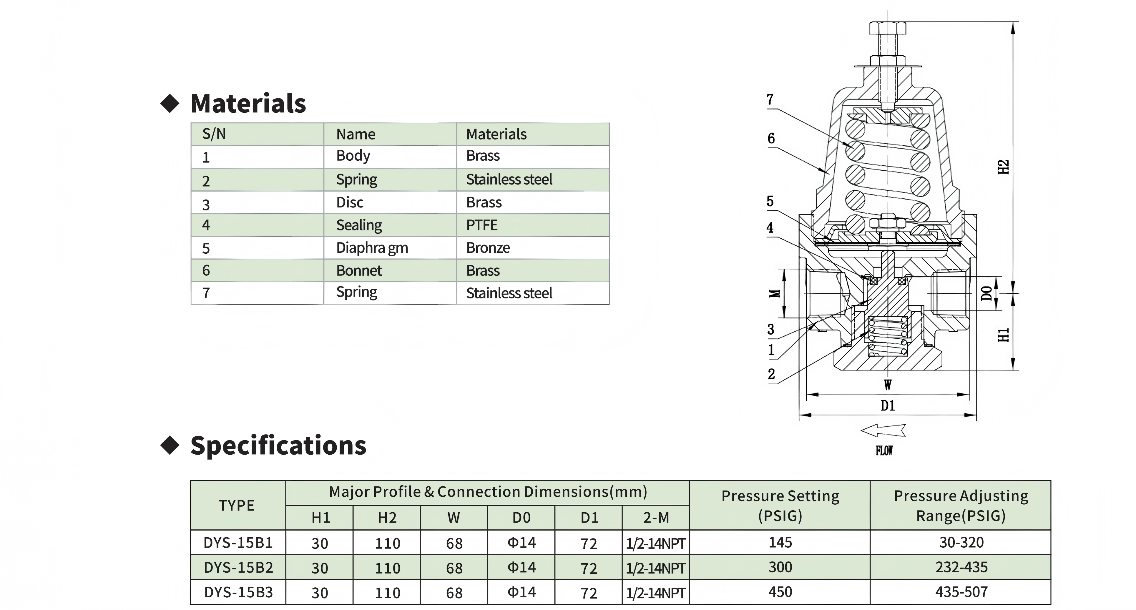
|
Comment & FAQ
1: Why is DYS15B so much taller (110 mm) than DYS15F (90 mm) when both are DN15?
A: The additional 20 mm of bonnet height is not a design choice—it is a physical necessity driven by spring mechanics. The B3 variant must deliver ~1700 N of preload at 507 PSIG. A spring capable of this force within a 90 mm envelope would require a wire diameter exceeding the coil-to-coil clearance, resulting in coil bind before the full adjustment stroke is reached. The 110 mm bonnet provides the column height necessary for the high-rate spring to operate through its full compression range without solid-stacking. The same tooling constraint applies to B1 and B2 because all three B-series variants share a common bonnet casting and spring guide geometry—economies of scale dictate one bonnet length for the family.
2. B3 adjusts to 507 PSIG, which equals the maximum inlet pressure. Is there any safety margin?
A: The 507 PSIG maximum inlet pressure rating accounts for the valve body's burst margin (typically 4:1 for brass pressure-containing components per ASME B31.3, yielding a theoretical burst pressure above 2000 PSIG). The B3's 435–507 PSIG adjustment range tops out at the rated inlet pressure by design—the valve is intended to serve as the final pressure-building stage in cascade systems where the upstream pressure source is the tank itself, not an external compressor or pump that could exceed 507 PSIG. The locknut serves as a mechanical stop that prevents field adjustment above the 507 PSIG ceiling; the adjusting screw runs out of thread before the spring can be compressed beyond the rated setting. If the application involves an external pressure source exceeding 3.5 MPa, the DYS15B is not the correct valve—a regulator with a higher inlet rating from a different product line should be specified.
3. Can I use DYS15B2 for a tank that operates at 200 PSIG?
A: No. The B2 adjustment range starts at 232 PSIG—there is a 32 PSI gap between the tank's 200 PSIG operating pressure and the lowest settable B2 pressure. Attempting to back the adjusting screw below 232 PSIG will cause the upper spring to unseat from its guide washer, resulting in erratic regulation or complete loss of set-point control. The B2 is designed for tanks operating in the 250–400 PSIG band. For a 200 PSIG tank, the DYS15B1 (30–320 PSIG) is the appropriate choice, or DYS15F2 (145–350 PSIG) if the B-series cost premium is not justified.
4. What is D1 = Φ72 mm, and why is it larger than other DYS variants?
A: D1 = Φ72 mm is the outer diameter of the body flange—the circular boss at the inlet/outlet face of the valve body that forms the sealing land against the mating pipe flange or fitting. In the DYS15B, this flange is substantially larger than the DYS15F's bonnet OD of Φ17 mm or the DYS15FM's D1 of Φ22 mm. The upsizing serves three functions: (a) it provides a wider gasket seating surface, reducing the gasket contact stress and the risk of extrusion at 507 PSIG; (b) the larger diameter distributes the bolt preload over a wider area, preventing brass flange warping under installation torque—a concern at the higher bolting forces required for 507 PSIG-class threaded joints; (c) the 72 mm flange provides a natural wrench flat for installation and removal, eliminating the need for a separate hex feature on the body. This is the same D1 dimension used on the DYS10A body (Φ57 mm), scaled up proportionally to the DN15 port size.
5. Is DYS15B suitable for LNG truck applications?
A: Technically yes—the valve functions identically on a vehicle-mounted tank. However, the DYS15B datasheet deliberately omits the "especially used in LNG tank of truck" language present in the DYS10A/DYS15F/DYS15FM documentation. This omission reflects the practical reality that mobile LNG trucks rarely require pressure-building regulation above 350 PSIG—their tank MAWP is typically 230–350 PSIG, and engine fuel supply pressure requirements are met comfortably by the DYS15F series. Installing a DYS15B on a truck adds unnecessary weight, height, and cost. The B series is purpose-positioned for stationary industrial installations: LNG/LCNG fueling station storage, peak-shaving plants, and industrial gas tank farms where higher storage pressures reduce boil-off gas losses and extend holding time between deliveries.
6.Are any internal parts shared between DYS15B and other DYS regulators?
A: The material specifications are identical across all DYS variants, but the physical dimensions are not interchangeable. The DYS15B's springs (components 2 and 7) have larger wire diameters and higher spring constants than any other DYS model. The diaphragm (component 5) may be the same C51000 bronze sheet but is likely a thicker gauge to resist the higher differential pressure across the membrane at the B3 ceiling. The body, bonnet, disc, and PTFE seal (components 1, 6, 3, 4) are specific to the B-series due to the 72 mm flange and deeper bonnet threads. From a service perspective, the DYS family now spans four distinct spare-parts kits: A-series (DN10), F-series (DN15 compact), FM-series (DN15 metric), and B-series (DN15 heavy-duty). Stocking the correct kit for the installed base is essential—a DYS15F spring installed in a DYS15B will fail to reach the rated set pressure, while a B-series spring in an F-series body may coil-bind before the adjustment screw reaches its lower stop.

 yongy0223@gmail.com
 +86-17693104145
 Lanzhou New Area, Lanzhou City, Gansu Province, on the second floor to the east of New Harbor Road, to the east of Building Materials Road No. 2, to the west of Qilian Mountain Avenue (Jingqi Road)


