

 |


loading


DJ61F-40P
SLDW
| Size: | |
|---|---|
| Availability: | |
| Quantity: | |
| Application Overview
The first two rounds — P1 (stainless + brass hybrid) and P (all-stainless) — are true deep-cryogenic liquid valves, rated to −198°C and capable of operating submerged in liquid nitrogen. This round's G/D series is not a deep-cryogenic liquid valve. Its temperature floor is −40°C — not much colder than a household freezer — and the service medium is explicitly stated as "Gas, such as Oxygen, Nitrogen, Argon, Carbon dioxide, NG" — not liquid. This is a gas-phase service valve.
The best framework for understanding G/D positioning is to divide a complete cryogenic storage and transport system into two temperature zones. The cold end encompasses the tank interior and liquid-phase piping — the medium is liquefied gas at −162°C to −196°C; the P1 and P series live here. The warm end encompasses the vaporizer downstream, vapor return lines, BOG (boil-off gas) compressors, and pressure-regulating stations — the medium has been vaporized and warmed, typically between −40°C and +85°C; the G/D series lives here. In the same storage system, liquid-phase and vapor-phase valves serve distinct roles: liquid-phase valves "withstand deep cryogenics"; vapor-phase valves "manage high flow rates."
The G/D series spans seven sub-models, from DN15 all the way to DN65 — the broadest coverage in the DJ61F-40P family. Cv stretches from 5 to 75 (DJ-65D), a full order of magnitude beyond the P series' DN25/Cv=14 ceiling. Flow priority is this series' foundational design logic — vapor-phase lines have far larger volumetric flow than liquid-phase lines (at the same mass flow, gas volume is roughly 200–600× liquid volume); controlling post-expansion gas with large-bore, high-Cv valves is an absolute requirement.
Model suffixes G and D alternate — DN15/25/32/40 are G, DN20/50/65 are D. The two letters likely represent two different temperature/pressure/end-connection schemes or branches from different revision histories. Since the source image does not elaborate on these suffix definitions, this document makes no hard assertions but provides an engineering judgment framework in the FAQ.
The bonnet connection method has also changed: the P series uses a screw bonnet; the G/D series uses a bolted bonnet. Bolted construction is more reliable than threaded construction at high pressures and large bores — a flange + bolt + gasket sealing path is easier to control for preload than a thread sealing path, and also easier to achieve uniform loading via tightening torque.
| Working Principle
Why does a "cryogenic" valve rated only to −40°C need to exist?
The first half of that sentence may sound counterintuitive — a valve marketed as cryogenic yet only rated to −40°C, nearly 160°C warmer than a true deep-cryogenic liquid valve. But this is precisely the G/D series' product logic: it is not built for liquid nitrogen.
Consider an LNG storage terminal. A complete process system comprises three temperature tiers. Tier 1 is the liquid-phase space inside the tank (−162°C) and the liquid-phase discharge piping — served by P1/P series or larger deep-cryogenic valves. Tier 2 is the gas-phase piping between the vaporizer outlet and the pressure-regulating station — the medium has just vaporized from liquid, temperature still well below 0°C but typically between −40°C and −20°C, no longer requiring the extreme low-temperature toughness of deep-cryogenic valves. Tier 3 is the ambient-temperature natural gas piping downstream of pressure regulation to end users — above 0°C, standard industrial valves suffice.
The G/D series is designed specifically for Tier 2. It does not pursue low-temperature impact toughness at liquid-nitrogen temperatures (which would double body and bonnet material costs), but it must maintain reliable sealing and operation at −40°C — a temperature range where ordinary carbon-steel valves experience ductile-brittle transition and uneven sealing-face contraction causing leaks, while the CF8 stainless + PCTFE combination is not only adequate but has generous margin.
The dimensional logic behind seven models
From DJ-15G to DJ-65D, this is a carefully spaced dimensional sequence. Look at Cv progression: 5 → 9 → 14 → 18 → 28 → 53 → 75. Adjacent model Cv ratios fall roughly between 1.4 and 1.9 — a reasonable engineering gradient ensuring each step up delivers a meaningful flow gain without the redundancy of two adjacent models being nearly equivalent in flow capacity.
More interesting is the B-value (flange height) step behavior: DN15/20 use B=68 mm, DN25/32/40 use B=12.7 mm, DN50/65 use B=16 mm. B does not grow continuously with bore; it steps discontinuously across three bore clusters. This aligns with pipe flange standard classification logic — DN1520 typically correspond to small-bore low-pressure flanges, DN2540 to ANSI 150# standard flanges, DN5065 to thicker reinforced flanges. The G/D series follows standard flange classification on B-value rather than self-defining — good news for procurement and spare-parts management, meaning on-site flange gaskets and bolts can be ordered as standard items.
Bolted bonnet: the leap from thread to bolt
The P1 series uses a screw bonnet; the P series the same. Screw bonnets offer compact structure and fewer parts; the disadvantage is that the thread sealing path's preload is difficult to control precisely — 1/8 turn too much can go from a good seal to over-torqued thread damage. DN1525 can tolerate this uncertainty, but on DN5065 large-bore valves, the bonnet's loaded area is 6–18× that of DN15, and thread sealing-face specific pressure control can leak with the slightest mismatch.
The G/D series adopts bolted bonnets uniformly across all seven models. This is a forward-looking decision for a large-bore platform: bolted flange connections, tightened sequentially by multiple evenly-spaced bolts, achieve controllable, uniform gasket specific pressure. Bolt thermal expansion/contraction management during pressure testing and cold operation of large-bore valves can be achieved through the elastic compensation of multiple bolts — thread connections cannot do this, because threads are rigid surface contact and cannot elastically compensate for thermal deformation.
The materials-science origin of the −40°C threshold
Why −40°C and not −30°C or −50°C? −40°C happens to be a classic demarcation threshold in ASTM and ASME codes for "low temperature" — above this temperature, the impact toughness of the vast majority of austenitic stainless steels (including CF8/304) resides in the upper-shelf region, with no ductile-brittle transition. In other words, −40°C is the natural boundary at which CF8 stainless "requires no additional low-temperature impact verification." The G/D series' choice of −40°C as the temperature floor means the valve can complete all certifications within a standard stainless material system, requiring no per-heat low-temperature impact testing as deep-cryogenic (−196°C) valves do — a significant advantage for volume production cost and lead time.*

|
Factory Shoot


|
Application Video
|
Product parameters


| Data Sheet
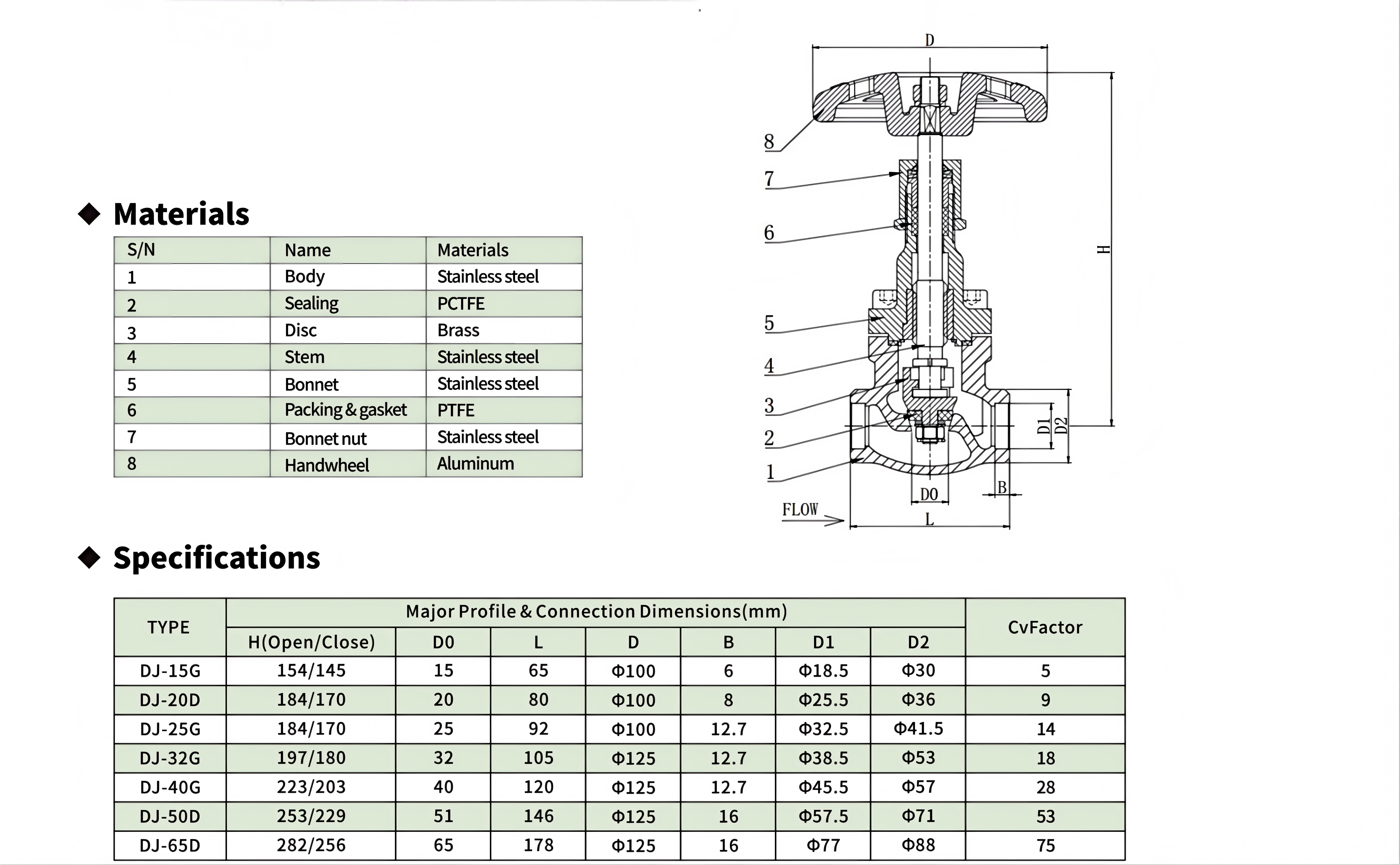
|
Comment & FAQ
1: Are the G/D and P/P1 series interchangeable?
A: Conditionally yes, but not blindly. The two series share identical interface dimension specifications (L/D0/D/D1/D2), so they are fully compatible at the physical installation level — pull a P series, install a G/D series, no pipe modification needed.
The reason they can't be freely interchanged is the temperature floor. P/P1 series are rated to −198°C, having passed deep-cryogenic impact and low-temperature seal qualification at the factory. G/D series are rated to −40°C, with cold-performance testing done only at −40°C. If you install a G/D series valve on a liquid-nitrogen line (−196°C), the CF8 stainless body and bonnet are fine at −196°C mechanically — CF8's ductile-brittle transition temperature is far below −196°C — but the PCTFE seat's contraction and contact stress at −196°C have not been validated. PCTFE's crystalline-phase behavior has subtle differences across temperature regimes; seal performance validated at −40°C cannot be risk-free extrapolated to −196°C. Conclusion: interchange toward colder (G/D replacing P/P1) carries risk; interchange toward warmer (P/P1 replacing G/D) is perfectly safe — a deep-cryogenic valve on a −40°C vapor line is downward-compatible overkill.
2: What distinguishes the G and D suffixes? How should I choose between e.g. DJ-25G and DJ-20D?
A: The source image does not explicitly define these suffixes, but two inferential clues can be extracted from the model lineup: Inference 1 — G and D may represent two different end-connection families. Observing the bore distribution — G series appears at DN15/25/32/40 (jumping in 25-base increments), D series at DN20/50/65 — the two families do not overlap in bore sizes. If G and D were merely different temperature ratings of the same valve, they should share the same bore range, but they don't, hinting that G and D may correspond to two different pipe-flange standards or weld-end dimension systems (e.g., G for GB flange series, D for ANSI). Inference 2 — from the B-value step behavior, both follow not different flange standards but natural grading within a single standard across bore ranges. DN1540 B steps from 6 to 12.7; DN5065 jumps to 16 — this is grading within one standard, not two. So G/D are more likely legacy naming artifacts than currently active technical differentiators. For selection: if your piping uses standard industrial diameters (DN15/25/32/40/50/65), first check the flange standard annotated on the piping design drawing and select by the standard-designated bore; the G/D suffixes can be ignored in this case. If the drawing has no standard annotation, match directly by nominal bore.
3 : What kind of gas flow can DJ-65D (Cv=75) actually handle?
A: Cv=75 is an enormous number on gas piping. Take a BOG compressor discharge line: assume −20°C natural gas (primarily methane), line pressure 1.0 MPa (gauge), downstream 0.7 MPa (gauge). Gas Cv conversion is more complex than liquid — involving compressibility factor and upstream/downstream pressure ratio. Below critical flow (P₂/P₁ > 0.5): Q(SCFH) = Cv × 22.67 × √(ΔP × P₁) / √(SG × T). Plugging in −20°C NG (SG≈0.55, T≈253K, P₁≈160 PSIA, ΔP≈44 PSI): Q ≈ 75 × 22.67 × √(44 × 160) / √(0.55 × 253) ≈ 12,100 SCFH ≈ 343 Nm³/h. Intuitive comparison: a household gas stove burns ~0.4 Nm³/h at full output. One DJ-65D valve can pass enough natural gas for roughly 850 stoves running simultaneously — enough to supply a mid-sized residential community. This is why the G/D series needs to go to DN65 — vapor-phase volumetric flow rates reach a scale where common industrial valves become insufficient.
4: Are the −40°C and −198°C PCTFE seats the same part number? Are they interchangeable?
A: From the materials table, P, P1, and G/D series all list the sealing element as PCTFE — same material designation. But "same material" ≠ "same part." The PCTFE seat's geometry — OD, ID, thickness, taper angle — must match its corresponding valve's disc and body sealing cavity. The P series (−198°C) and G/D series (−40°C) seats may have identical nominal dimensions at room temperature (since they share the same D0 and body platforms at DN15 and DN25), but the actual compression and sealing specific pressure at low temperature have been validated across different design ranges. Conclusion in two layers: Physically — the DN15 and DN25 PCTFE seats are very likely the same part number across P/P1/G/D — all four series share identical D0 dimensions at DN15 and DN25; no need for two sets of tooling. DJ-15P/P1/G seats should be the same part number; DJ-25P/P1/G the same. Certification-wise — P/P1 PCTFE seats have been validated for sealing at −198°C; G/D seats only to −40°C. Even if physically the same part, if you install a PCTFE seat pulled from a G/D series valve onto a deep-cryogenic liquid line, whether it achieves bubble-tight seal at −196°C is not certifiably assured.
5: Bolted bonnet vs. screw bonnet — when to choose which?
A: The answer emerges from the DJ61F-40P family's own evolution: For DN1525 — P, P1, and G/D all offer this bore range; P/P1 uses screw bonnet, G/D uses bolted bonnet. This tells us both are viable at small-to-medium bores — screw bonnet is more compact and lighter; bolted bonnet is more reliable and easier to maintain. The choice depends on maintenance strategy: if the valve location is easily accessible with high maintenance frequency, prefer screw bonnet for quick bonnet removal without unbolting; if the valve is at height or confined space requiring ladder access, prefer bolted bonnet (unbolting is safer and more controllable than torquing large threads on a ladder). For DN3265 — screw bonnet is no longer practicable at this bore range; a DN65 threaded bonnet would require tightening torque in the hundreds of N·m, not feasible in field installation and maintenance. The G/D series' uniform adoption of bolted bonnets at DN32 and above is sound engineering.
6: Which of the seven models are most commonly used? Which are "gap-fillers"?
A: Cv spacing reveals the gap-filling degree. Models with genuinely independent engineering value are those with clearly separated flow capability. DJ-15G (Cv=5), DJ-25G (Cv=14), DJ-40G (Cv=28), DJ-65D (Cv=75) — these four have roughly 2× spacing in Cv, each a meaningful tier jump. DJ-20D (Cv=9) sits between DJ-15G (5) and DJ-25G (14) — the gap doesn't open enough independent selection space. Its existence is more likely to match DN20 pipe diameter (DN20 is a standalone spec in some pipe-flange standards). DJ-32G (Cv=18) and DJ-50D (Cv=53) are similar cases — if the line happens to be DN32 or DN50, having a matching-size valve is more economical than using a DN40 or DN65 with reducer flanges. From an inventory perspective: stocking DJ-15G/DJ-25G/DJ-40G/DJ-65D covers the full range from small to large. Add DN20/32/50 on demand.

 yongy0223@gmail.com
 +86-17693104145
 Lanzhou New Area, Lanzhou City, Gansu Province, on the second floor to the east of New Harbor Road, to the east of Building Materials Road No. 2, to the west of Qilian Mountain Avenue (Jingqi Road)


