

 |


loading


Fittings
SLDW
| Size: | |
|---|---|
| Availability: | |
| Quantity: | |
| Application Overview
In a cryogenic piping system, valves are the "switches" and regulators are the "brain" — pipe fittings are the "skeleton." A valve's performance envelope is defined by its own design and materials, but the overall system's hermeticity, flow-resistance distribution, and assembly maintainability rest largely on the fittings. One wrong connector can cause a line to leak simultaneously from three different ports after cooldown — and tracing such leaks is far harder than diagnosing a valve-body fault.
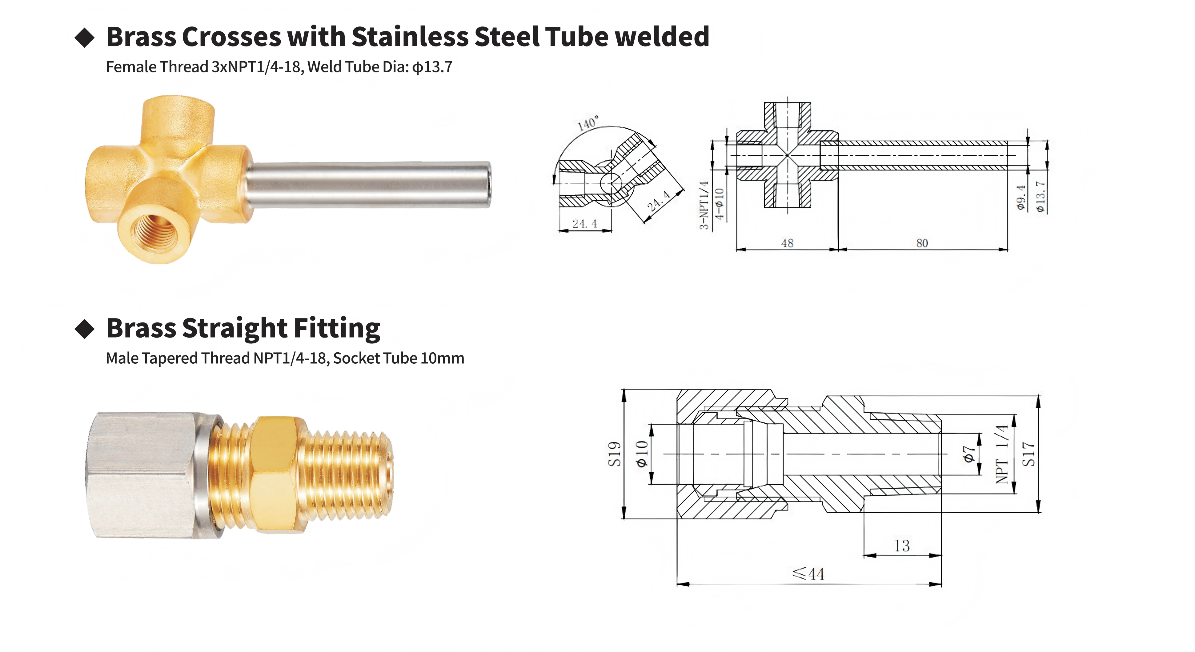
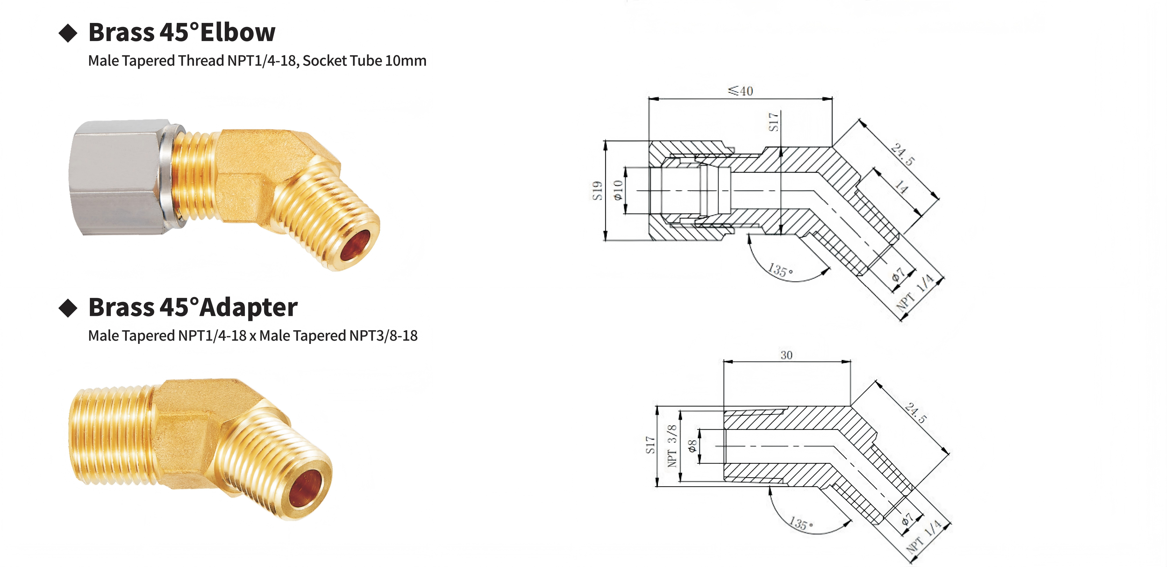
This four-piece brass fitting series covers the four most common connection scenarios in cryogenic piping: cross-flow branching (Brass Crosses with Stainless Steel Tube welded), straight-through transition (Brass Straight Fitting), 45° direction change (Brass 45° Elbow), and size-reducing directional transition (Brass 45° Adapter). All four feature brass bodies, with NPT tapered pipe threads on the connection side and two forms on the tubing side — φ10 mm ferrule-type hard-tube ports and a φ13.7 mm stainless steel weld tube.
Brass's role in cryogenic fittings is often underrated. Stainless steel looks "more premium" for fittings, but in real-world installation, brass has two practical advantages stainless does not: self-lubricating threads — brass has a lower friction coefficient, so NPT taper threads tighten without galling and remain smooth after multiple make-break cycles; and moderate thermal conductivity — brass conducts heat roughly seven times better than stainless. In ambient-temperature lines this is a drawback (more heat loss), but at LNG temperatures it is neutral — the fitting itself does not need to hold cold (the pipe insulation layer does that), and brass's heat conduction actually helps the fitting reach thermal equilibrium faster during cooldown, reducing interface stress caused by the fitting and pipe cooling at different rates.
The ferrule-type (socket-type) interface deserves the deepest attention in this series. A φ10 mm socket connection is not simply "insert the tube and tighten" — it is a metal cold-extrusion sealing system: as the nut tightens, the ferrule's front cutting edge bites into the tube's outer wall by about 0.1–0.2 mm, forming a 360° metal-to-metal seal ring. The rear edge simultaneously grips, providing anti-vibration locking. This sealing method is far more reliable than O-ring seals at cryogenic temperatures — O-rings harden and lose elasticity at −196°C, while the ferrule's cold-extruded seal ring is unaffected by temperature, and sealing force actually increases as the metal contracts in the cold.
| Working Principle
All threaded ends across the four fittings use NPT (National Pipe Taper) threads, 18 threads per inch. NPT threads seal without gaskets or O-rings — they seal via the thread itself. Both male and female threads are tapered (1:16 taper); as they tighten, the male thread wedges into the female, generating metal-to-metal contact pressure between thread crest and root. This pressure distributes along the entire thread engagement length, forming a continuous helical seal line.
But counterintuitively: the NPT seal surface is not on the thread crest — it is on the thread flank. After tightening, the male and female flank surfaces are compressed together, forming a face-contact seal. There is actually a micro-gap between crest and root — this is not a defect; it is the space reserved for sealant (thread compound or PTFE tape). The correct installation method is to wrap PTFE tape 3–4 turns clockwise (matching the tightening direction); the tape compresses between male and female threads into a fill film roughly 0.05–0.08 mm thick, filling the crest-root gap.
Hand-tighten 2–3 turns, then wrench-tighten another 2–3 turns — NPT threads do not need to be tightened until the hex flats touch. Over-tightening merely splits the female thread and does not increase seal quality.
Cold-extrusion sealing of ferrule-type connections
The φ10 mm socket connection on the straight fitting and 45° elbow is a dual-action cold-extrusion system. After inserting φ10 mm hard tubing (stainless steel or annealed copper) and tightening the nut, the internal ferrule undergoes a two-step process:
Step one — front-edge bite. The nut drives the ferrule down along the taper; the ferrule's front cutting edge (~30° acute angle) bites into the tube's outer wall to a depth of roughly 0.1–0.2 mm. This is not cutting — it is cold extrusion: tube-wall material is displaced sideways by the front edge, forming a raised seal lip that presses firmly against the ferrule's inner taper.
Step two — rear-edge grip. Once the front edge is fully seated, continued tightening causes the ferrule's mid-section to elastically flex, pulling the rear edge inward to grip the tube wall. The rear edge's role is not sealing but locking — preventing the tube from axially pulling out under pipeline vibration or thermal expansion-contraction.
After both steps complete, there are two independent annular contact bands: the front-edge metal-to-metal seal ring (gas-tight) and the rear-edge mechanical lock ring (vibration-resistant). Both rings tighten further under cold contraction at −196°C, eliminating the risk of O-ring low-temperature hardening failure.
Fluid-mechanics rationale for 45° elbows
Why 45° and not 90°? In LNG cryogenic lines, a 90° elbow introduces two problems: excessive local resistance coefficient (~0.75–1.0 for 90°, versus ~0.3–0.4 for 45°) and cavitation risk at the inner bend. LNG is near saturation; the local low-pressure zone created at the inside of a 90° elbow as streamlines bend can trigger flashing — liquid methane locally vaporizes into bubbles at the elbow, and these bubbles collapse in the downstream pressure-recovery zone, producing continuous micro-hammer impacts. A 45° elbow has a larger streamline curvature radius and gentler velocity-direction change; its low-pressure zone is both smaller in extent and shallower in depth, making it far safer in LNG near-saturation-pressure service.
Flow distribution logic of the cross fitting
The cross fitting (3 × NPT 1/4" female + φ13.7 stainless steel weld tube) is fundamentally a three-in-one-out collection node. The three threaded ports are three independent gas-phase branch inlets; the weld tube is the combined outlet. The 140° arm angle means the three ports are not equally spaced at 120° — they are distributed within a 140° sector on the opposite half of the weld tube. This is an offset-collection design: the three inlets cluster in the 140° sector directly opposite the weld tube, which sits at the geometric centroid of this small sector, making the flow-path length from each branch to the weld tube nearly equal, minimizing pressure interference between branches.
The stainless steel weld tube is joined to the brass cross body by brazing, not threading. Brazing was chosen over fusion welding because the two metals have different thermal expansion coefficients — brass ~19×10⁻⁶ /°C, stainless ~17×10⁻⁶ /°C. Brazing temperatures (~650–850°C) are far lower than fusion welding (>1400°C); the heat-affected zone is smaller, post-weld residual stress is lower, and the joint is far less likely to crack under repeated thermal cycles from the thermal stress differential.*

|
Factory Shoot


|
Application Video
|
Product parameters


| Data Sheet
|
Comment & FAQ
1: Can all four fittings be used for LOX?
A: Brass as a body material poses no reactivity risk with LOX; neither NPT threads nor ferrule structures contain organics. But two items require separate verification: factory degreasing status and on-site secondary contamination control. Ferrule fittings may retain trace cutting oil from machining; if "oxygen clean" was not specified, ultrasonic-clean all flow paths with anhydrous ethanol or isopropanol before use and assemble in a grease-free environment. For the stainless weld tube end, likewise ensure the tube interior is free of grease before welding.
2. How tight should the ferrule nut be? Is there a recommended torque value?
A: There is no universal torque value for ferrule fittings — torque depends on tube hardness, ferrule material, and thread lubrication, and is not a fixed number. The standard judgment method is turn-counting: finger-tighten until the ferrule first contacts the tube (you'll feel resistance suddenly increase), then wrench-tighten an additional 1¼ turns. After tightening, loosen the nut and inspect the tube outer wall — you should see a uniform, continuous ferrule bite mark around the circumference, with no gaps or depth inconsistency. If the mark is intermittent, the front edge bit unevenly; re-assemble with a new ferrule (the used one is no longer reusable).
3. Can the ferrule ports on the straight fitting and 45° elbow accept stainless steel tubing, or only copper?
A: Both. The ferrule front-edge hardness must exceed the tube material hardness — brass ferrule hardness is roughly HRB 60–70, and annealed 304 stainless steel tube is roughly HRB 70–85. In this hardness range, the brass ferrule's front edge can still bite into stainless tube's outer wall and form an effective seal, though the bite depth will be slightly shallower than on soft copper (~0.08–0.12 mm vs. ~0.15–0.2 mm). The critical requirements: tube OD tolerance must be within φ10 ±0.1 mm, surface finish Ra ≤ 0.8 μm — any scratches or out-of-roundness beyond tolerance will cause a discontinuous ferrule seal ring.
4. Are NPT 1/4" and NPT 3/8" interchangeable? Can the 45° adapter be used in reverse?
A: Not interchangeable — although both are standard NPT family sizes, NPT 1/4" and 3/8" have completely different thread ODs and pitches. Male 1/4" major diameter is ~13.7 mm; 3/8" is ~17.1 mm. Attempting to thread one into the other will only damage the threads. The 45° adapter has NPT 1/4" on the large end and NPT 3/8" on the small end. Using it in reverse (large end into a 3/8" female, small end into a 1/4" female) is physically impossible. If the system genuinely needs a 3/8"→1/4" reduction, a dedicated straight reducer fitting should be purchased instead of trying to flip this 45° adapter.
5. Can the stainless steel weld tube on the cross fitting be cut shorter or bent?
A: Cutting shorter is fine; bending is not. The weld tube has relatively thin walls (φ13.7 mm OD, estimated wall 1.0–1.5 mm); cold-bending with a tube bender would produce inner-wall wrinkling and outer-wall thinning, seriously compromising pressure capacity. The correct approach: straight-cut to the desired length with a tube cutter, deburr, then weld directly. When welding after cutting, note one parameter: the tube insertion depth into the brazed joint should be at least 1.5× the tube diameter (~20 mm), and the weld zone must be free of oil — a universal iron rule for LNG line welding.
6. Can the 45° elbow and straight fitting be threaded directly onto cryogenic valves?
A: Is there a galvanic corrosion risk from dissimilar materials? Yes. Brass fitting to brass valve body is a zero-galvanic-potential pair (same material). Stainless steel to brass is also a very small galvanic potential difference (~0.15V); in a dry LNG gas-phase environment, the corrosion rate is practically negligible. The only scenario warranting attention is moisture-containing gas-phase lines — if the medium contains trace moisture (e.g., air purge lines at fueling stations), brass-to-stainless couples in humid conditions may experience galvanic corrosion. For fully dry LNG / LN₂ / LAr lines, this is a non-issue.

 yongy0223@gmail.com
 +86-17693104145
 Lanzhou New Area, Lanzhou City, Gansu Province, on the second floor to the east of New Harbor Road, to the east of Building Materials Road No. 2, to the west of Qilian Mountain Avenue (Jingqi Road)


