

 |


loading


DJ61F-40P
SLDW
| Size: | |
|---|---|
| Availability: | |
| Quantity: | |
| Application Overview
After globe valves (DJ61F) and emergency shut-off valves (DJ661F), the catalog turns to the most structurally minimalist yet mechanically subtle product in the valve lineage: check valves. The model prefix DH61F-40P — DH replaces DJ, H standing for Check, the fourth letter to debut in the family naming system.
The DH61F-40P is a spring-loaded lift-type cryogenic check valve designed for marine piping, industrial pipelines, and LNG systems. Its core function is ruthlessly simple: allow medium flow in one direction, automatically close on reversal. No handwheel, no air supply, no electricity, no operator — flow itself is the actuator.
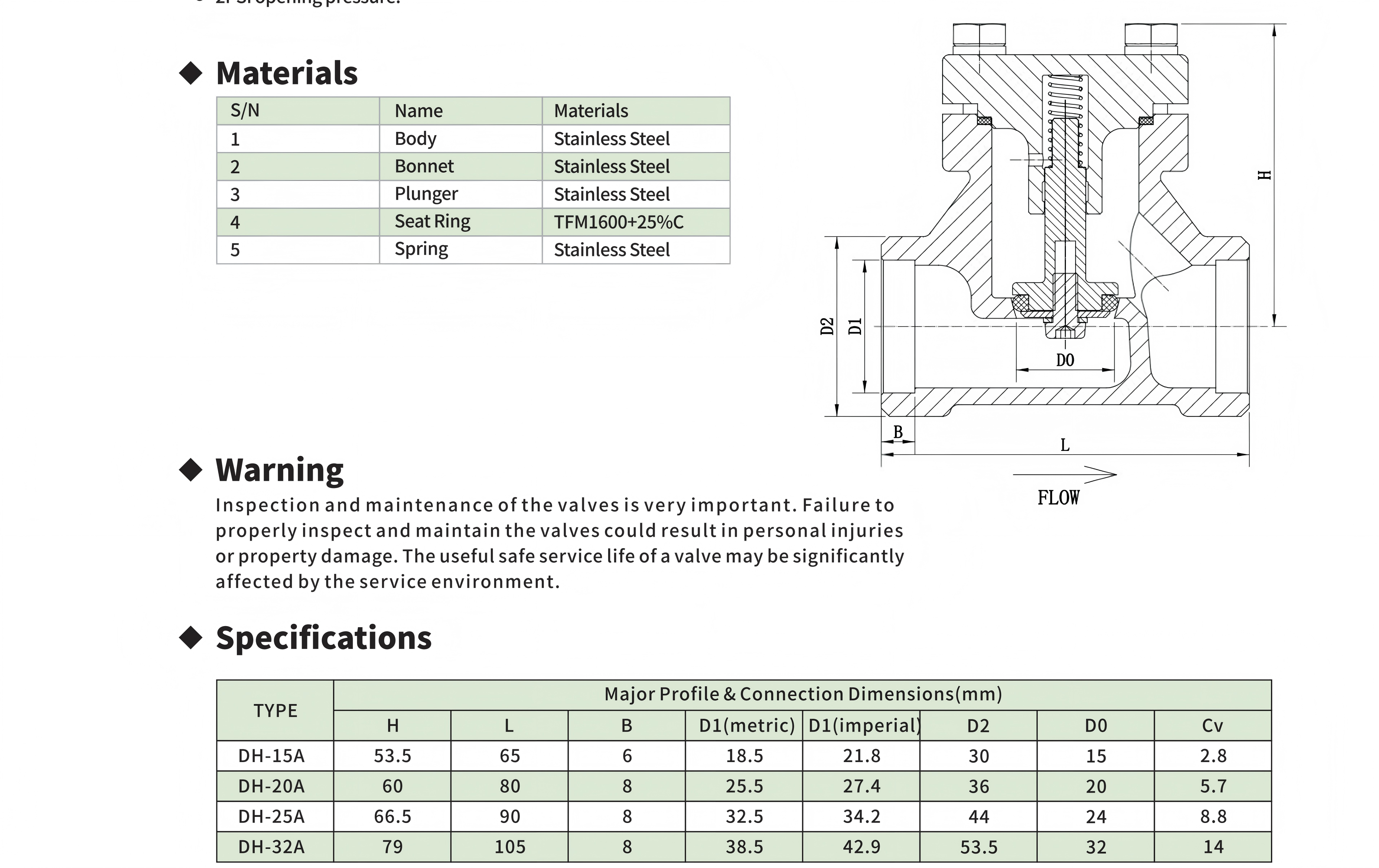
But it is precisely in this extreme simplicity that the design's restraint becomes admirable. The entire valve comprises only 5 parts (body, bonnet, plunger, seat ring, spring) — nearly half the globe valve's 8, and a mere fraction of the emergency shut-off valve's 16. Four of the five are stainless steel; the remaining one — the seat ring — is the single most expensive component in the entire valve: TFM1600 + 25% carbon fiber fill, a modified PTFE composite.
Four models cover DN1532, with overall heights of only 53.579 mm — about the height of a marker pen. This flat profile is not accidental — the check valve has no stem penetrating the bonnet (the plunger is fully enclosed within the body), requiring no stuffing box, no actuator, no extended bonnet. All moving parts live inside the body, managed entirely by the flowing medium.
The DH61F-40P and the earlier DH15F check valve belong to the same product category but different tiers: DH15F is an economy brass-body + PTFE-seal design; the DH61F-40P is a premium all-stainless + bolted-bonnet + TFM1600-seat platform. 600 PSI rating, CGA G-4.1 oxygen cleaning, −196°C to +85°C temperature coverage — it targets nodes in LNG/LN2/LO2 piping where reliability and maintainability are rigid requirements.
| Working Principle
Fluid-mechanical self-governance: the physics of opening and closing
The DH61F-40P's operation can be described as a simple force balance. At rest, the spring presses the plunger against the seat ring with a preload equivalent to 2 PSI. When medium enters from the left (inlet) at a differential pressure exceeding 2 PSI, fluid dynamic pressure acts on the plunger's bottom projected area, generating upward lift. Once lift exceeds spring preload, the plunger rises, and fluid flows through the annular gap between plunger and seat.
The plunger's upward travel is limited by the bonnet's internal cavity — the bonnet's lower section is machined with a cylindrical guide bore in which the plunger's cylindrical segment slides. This guide bore serves two functions: ① keeping the plunger concentric with the seat throughout its lift stroke (self-centering), preventing off-axis tilt that causes uneven sealing face wear; ② acting as the plunger's stop during reverse flow — the plunger, pushed back by the spring, does not over-insert into the seat; force and travel terminate at the seat, not in the spring or plunger.When inlet pressure drops or downstream pressure exceeds upstream, the reverse differential pressure plus spring force pushes the plunger back onto the seat ring, and the sealing face contacts the plunger's bottom surface — seal established. The key here: the greater the reverse pressure, the greater the sealing force — this is not achieved by the spring alone but by the superposition of reverse differential pressure and spring force. 2 PSI is only the cracking threshold; reverse sealing capacity is dictated by the 600 PSI rated pressure.
TFM1600 + 25%C: the seat ring material selection logic
The seat ring is the single most expensive component in the DH61F-40P — not because the material itself is costly, but because this specific compound formulation is far less common in cryogenic valves than standard PTFE or PCTFE. TFM1600 is a chemically modified PTFE variant: perfluoroalkyl vinyl ether (PPVE) is introduced as a comonomer during polymerization, resulting in branched molecular chains that reduce folding defects during main-chain crystallization; the final product's porosity is roughly 1~2 orders of magnitude lower than standard PTFE.
Low porosity matters more in check valves than in globe valves. A globe valve seat experiences compressive force only while the valve is closed and is unloaded the rest of the time; a check valve seat ring is under continuous spring pressure during any non-flow state (only 2 PSI, but 24×365 cumulative effect is significant). High-porosity PTFE under such sustained static load undergoes cold flow — material slowly migrates from a compressed region to an uncompressed region, altering sealing surface topography and reducing sealing force. TFM1600's low porosity directly fights cold flow.
25% carbon fiber fill is the second critical choice. Carbon fiber's role is not strength enhancement (the seat ring does not bear structural loads) but three categories of engineering improvement:
Thermal conductivity:Carbon fiber's thermal conductivity far exceeds the PTFE matrix. If the plunger flutters under low flow, friction-generated heat dissipates through carbon-fiber conduction, avoiding localized hot spots.
Wear resistance:The check valve plunger slides along the seat ring's inner bore surface on every actuation cycle (lift-type check, the plunger has a guided sliding travel within the seat ring bore), and carbon fiber provides a hard wear-resistant phase.
Dimensional stability: Carbon fiber's low thermal expansion coefficient constrains PTFE matrix expansion/contraction during temperature changes; the seat ring's dimensional change from room temperature to −196°C is more controllable than pure PTFE, reducing preload loss at cryogenic temperatures.
Stainless steel plunger vs brass disc: check valve and globe valve material divergence
The DH61F-40P's plunger is stainless steel, while the DJ61F-40P globe valve family's discs are uniformly brass. This is not an arbitrary choice — the two valve types subject the closure element to entirely different force regimes.
A globe valve disc is forcibly pressed into the seat by the stem, with the closing torque coming from the handwheel's screw transmission; the force magnitude depends on the operator's hand effort. Brass's advantage here: ① it is softer than stainless steel; even if the operator overtightens, brass yields before the seat, sacrificing the disc to protect the seat (a replaceable disc is easier to service than an integrated body-seat); ② brass-to-stainless stem pairing has superior anti-galling performance compared to stainless-to-stainless.
A check valve plunger is not externally driven — it is lifted by flow pressure, pressed back by the spring. Closing force is spring force + reverse differential pressure, neither excessive nor insufficient. The plunger slides within the bonnet guide bore; stainless-to-stainless self-centering sliding requires precise clearance fit — too loose causes tilt, too tight causes jamming. The DH61F-40P's "self-centering" characteristic indicates the tolerance design between the plunger's cylindrical segment and the bonnet guide bore is sufficiently precise.
Another argument for the stainless plunger: there is no brass-to-stainless threaded pair inside the check valve (the globe valve's stem thread rotates within the bonnet), so no anti-galling requirement exists. And the all-stainless material uniformity eliminates galvanic corrosion risk — if the plunger were brass and the body stainless, in humid or chloride-containing environments, the brass would act as the anode and suffer preferential corrosion.
Dual-track D1: the design intent behind coexisting metric and imperial bores
The DH61F-40P dimension table exhibits a rare feature: D1 is listed with two values — metric and imperial. Taking DH-15A as an example, metric D1=Φ18.5, imperial D1=21.8 mm. These two values do not mean the same body has two different bores — they indicate the body can have its end connections machined to match two pipe outer-diameter standards.
Metric D1 corresponds to ISO metric pipe OD (DN15 → OD 21.3 mm → ID approximately 18.5 mm after subtracting wall thickness); imperial D1 corresponds to ANSI/ASME pipe sizing. The presence of dual-track D1 indicates the DH61F-40P was designed from the outset to accommodate, on the same body casting, different weld-end machining to match metric or imperial piping — common engineering practice for export-oriented products: the valve's installation dimensions (L/B/D2/D0) remain unchanged, only the weld bevel dimensions at the end connections are selected per the customer's pipe standard.
Why only DN15~32? Where are DN40 and DN50?
The DJ61F-40P globe valves cover DN15~65 across seven bores, but the DH61F-40P check valve stops at DN32. This is not a technical capability limitation but a law-of-physics limitation.
A lift check valve's plunger must be lifted by flow pressure — and the lifting force from flow pressure is proportional to the plunger's projected area (∝ D²), while the plunger's weight (in vertical installation, plus its own gravity) is proportional to volume (∝ D³). From DN32 to DN40, bore increases 25%, but plunger weight increases approximately 95% (D³ growth), while projected area increases only 56% (D² growth). Under low-flow conditions — for instance, the initial filling phase of an LNG tanker, where flow may be only 10~20% of rated capacity — an excessively heavy plunger may not be reliably lifted by flow pressure, or, once lifted, may frequently drop back due to flow fluctuations, generating water hammer.
The practical upper limit for lift check valves is generally around DN50. Beyond this bore, industry switches to swing check valves or axial-flow check valves, using the plunger gravity's pivot moment to balance flow pressure rather than directly opposing a linear spring + gravity force. The DH61F-40P stopping at DN32 is a pragmatic engineering decision: where large-bore check valves are needed, route to a different check valve type.*

|
Factory Shoot


|
Application Video
|
Product parameters


| Data Sheet
|
Comment & FAQ
1: What is the relationship between DH61F-40P and the earlier DH15F check valve? Which to choose?
A: Same product category, different positioning. DH15F is a brass-body + PTFE-seal economy platform, DN15 bore only, for ambient or moderate-cold applications. DH61F-40P is an all-stainless + TFM1600 carbon-fiber-seat premium platform, DN15~32 across four bores, for deep cryogenic (−196°C) and high-pressure (600 PSI) applications. Material differences dictate application boundaries: brass body impact toughness drops sharply at −196°C (FCC metals have no DBTT, but the β phase in cast brass embrittles at low temperature), unsuitable for deep-cryogenic liquid service; DH61F-40P's CF8 stainless body maintains Charpy values above 40J at −196°C. If your line carries LO2/LN2/LNG, choose DH61F-40P. For ambient CO2 or compressed air, DH15F suffices.
2: Can the 2 PSI cracking pressure be adjusted?
A: My line needs lower resistance or higher backflow sealing force. 2 PSI is achieved by spring preload — changing to a spring with different stiffness alters the cracking pressure. But three points must be clear: ① Cannot be dialed down to 0 — a check valve needs minimum spring force to ensure the plunger quickly re-seats at the onset of reverse flow; otherwise "floating closure" occurs — reverse flow has already begun but the plunger hasn't seated yet, the medium backflows during this window, the sealing face gets eroded, leading to long-term seal failure. ② Increasing it reduces Cv — the higher the cracking pressure, the greater the spring force to overcome during normal flow, the lower the plunger lift, the smaller the flow area, and actual Cv falls below rated. If you need 5 PSI cracking, the DH-15A's actual flow may drop below half of its rated Cv 2.8. ③ Spring replacement requires manufacturer compatibility confirmation — the spring's installation geometry (spring cavity depth, compressible distance between plunger and bonnet) is fixed; only springs with the same installation geometry but different K values can be substituted. DIY spring cutting is absolutely prohibited — it alters the spring end-face flatness, causing eccentric plunger loading.
3 : Is there a required installation orientation? Vertical or horizontal?
A: Recommended installation: horizontal piping, bonnet facing upward. The rationale: spring force is always vertically downward, plunger gravity is also vertically downward — spring force and gravity align, and the net force on the plunger at any lift position is most stable. Vertical installation (flow bottom-to-top) is acceptable, but the condition changes: the plunger must overcome both spring force + its own weight (not spring force alone), so actual cracking pressure exceeds 2 PSI. Vertical installation (flow top-to-bottom) is absolutely prohibited — this is a fatal installation orientation for check valves: the combined gravity + spring force presses the plunger into the seat, requiring far more than 2 PSI differential to lift; and once lifted, plunger return relies on spring force minus gravity (not spring force plus gravity), slowing closure and potentially allowing reverse flow to enter before the valve closes.
4: Cv is much lower than same-bore globe valves — is this pressure drop acceptable in LNG lines?
A: Take DH-25A (Cv=8.8) vs DJ61F-40P same-bore globe valve (Cv=14, DN series). The ~37% gap originates from two physical effects: ① Spring force — the check valve plunger needs flow pressure to continuously overcome spring force to stay open, while a globe valve's disc, once opened, stays at the full-open position (mechanically locked by the stem). At the same flow velocity, the check valve's effective flow area is always discounted by one spring-compression stroke versus the globe valve. ② Flow-path geometry — the check valve plunger sits in the center of the flow path, and fluid must flow around it through an annular gap — this is an abrupt streamline curvature, producing greater form-drag loss than a globe valve (where the disc is offset to one side, with a straighter main flow path). Whether this extra pressure drop is acceptable in an LNG line depends on the application scenario. For main tanker loading/unloading lines (high flow, large pipe diameter), the pressure drop is tens of kPa — completely acceptable, even a single elbow loses more. For instrument lines or low-flow bypasses (flow near the Cv curve's knee), the pressure drop could become a bottleneck — in this case, calculate the specific flow and pressure drop, and upsize one bore if necessary.
5: The spring is stainless steel — does spring force change at low temperature? What is the spring's material grade?
A: The spring's K-value change at low temperature comes from two effects: ① Stainless steel's shear modulus G increases slightly with decreasing temperature (at −196°C, 35% higher than at room temperature, depending on specific grade), meaning the spring "stiffens" at low temperature — closing force increases, cracking pressure rises slightly; ② Spring wire has no DBTT issue (austenitic stainless steel has none), so no low-temperature brittle fracture risk. Net effect: from room temperature to −196°C, cracking pressure rises from 2 PSI to approximately 2.1 PSI — well within engineering tolerance and does not affect valve performance. The spring material is most likely 302 or 304 stainless spring wire — both are universal choices for cryogenic valve springs. 316 is viable but costs more with no material low-temperature performance advantage.

 yongy0223@gmail.com
 +86-17693104145
 Lanzhou New Area, Lanzhou City, Gansu Province, on the second floor to the east of New Harbor Road, to the east of Building Materials Road No. 2, to the west of Qilian Mountain Avenue (Jingqi Road)


