

 |


loading


DJ61F-40P
SLDW
| Size: | |
|---|---|
| Availability: | |
| Quantity: | |
| Application Overview
The DJ61F-40P is the DJ series' weld-end platform targeting permanently installed piping systems. The earlier DJ10 and DJ15A are NPT-threaded connections suited to Dewars and Mini-Bulk tanks where frequent disassembly is expected. The DJ61F-40P is fundamentally different — it joins the pipeline via socket weld or butt weld, not designed for later removal. This is "permanent-installation-grade" product positioning.
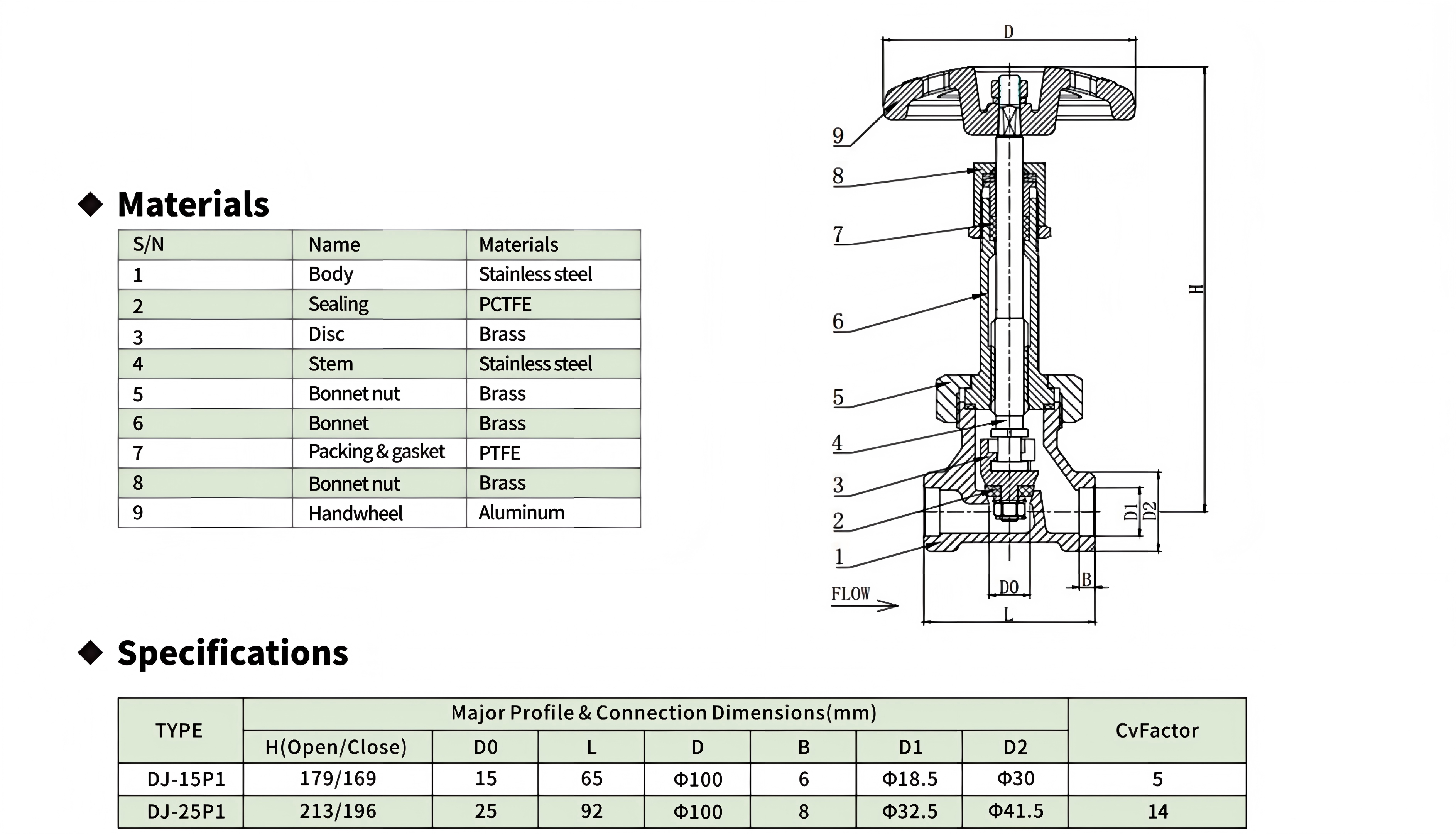
The model number itself encodes key design information: DJ = cryogenic globe valve series, "61" = weld-end construction, "F" = fluoroplastic seal (PCTFE / PTFE), "40P" = nominal pressure 4.0 MPa. P1 is the platform code, with two sub-models: DJ-15P1 (DN15, Cv=5) and DJ-25P1 (DN25, Cv=14).
Three tiers of upgrades establish this platform's high-flow positioning. First: bore size — the DJ-25P1 is the first DN25 globe valve in the product family, with Cv=14 providing roughly 2.8× the flow capacity of the DJ-15P1, sufficient for trailer loading/unloading at industrial flow rates. Second: weld ends — socket weld and butt weld options cover the full spectrum from high-pressure small-bore to large-bore thin-wall piping. Socket weld suits compact DN15 and below lines; butt weld suits DN25 and above continuous piping. Third: top-entry serviceable design — the bonnet threads into the body, allowing the bonnet, stem, and disc assembly to be extracted from the top for seal replacement without removing the valve from the welded line. No pipe cutting, no downstream media venting, no re-welding — maintenance time compresses from hours to tens of minutes.
The materials strategy extends the DJ15A's logic with greater precision: body in ASTM A351 CF8 (cast 304 stainless steel), bonnet and bonnet nut in brass, disc in brass with PCTFE soft seat, packing and gasket in PTFE. The same stainless + brass hybrid philosophy — but the explicit CF8 grade annotation signals that this valve targets formal engineering procurement scenarios requiring material traceability. Not a spare part picked off a shelf; it is a pipeline component whose material grade belongs on the P&ID.
| Working Principle
Three pillars supporting a weld-end platform
The DJ61F-40P shares the same fundamental open/close mechanism as other DJ-series globe valves — handwheel rotation drives the stem axially, bringing the disc's conical face into contact with or away from the PCTFE seat. But the design center of gravity is not in the actuation mechanism itself. It is in how two seemingly contradictory goals — permanent weld installation and in-line maintainability — coexist in one design. Three pillars support this scheme.
Pillar 1: top-entry serviceable architecture.With a traditional welded valve, once it is welded into the line, maintenance means cutting the pipe — sever the welds on both ends, extract the valve, service it on a bench vise, weld it back. The entire process involves hot work, line purging, and post-weld NDT. The DJ61F-40P's bonnet threads into the body; after loosening the bonnet nut, the entire bonnet assembly (handwheel, stem, disc) can be withdrawn from the body in one piece, exposing the PCTFE sealing seat and PTFE packing — while the body remains welded in the line. No pipe cutting. Once the seal is replaced, thread the bonnet assembly back into the body and re-tighten. In welded-pipe-dense environments like trailer loading arms and tank pipe galleries, this structure is highly valuable — the annual routine PCTFE seal replacement goes from "half a day of shutdown" to "half an hour of shutdown."
Pillar 2: the engineering logic of weld-end selection.Socket weld vs. butt weld is not a binary "which is better" question — it is an engineering decision jointly determined by pipe diameter and pressure class. In socket weld, the valve body end features a socket bore; the pipe is inserted, and a fillet weld is made between the pipe OD and body face. Advantages: easy alignment, low welding distortion. Disadvantage: the socket clearance (~0.4–0.8 mm) can develop crevice corrosion after cryogenic contraction. In butt weld, the body end and pipe end are aligned edge-to-edge, with a full-penetration butt weld. Advantages: zero clearance, radiographable, highest strength. Disadvantages: strict alignment required, welding distortion needs control. For DJ-15P1, with its small DN15 bore and relatively thick wall, both methods are viable — if line cleanliness requirements are high (e.g., LOX), prefer butt weld to avoid a dead zone in the socket clearance. For DJ-25P1, with its larger DN25 bore and higher joint forces, butt weld is the more sensible choice — a full-penetration 25 mm butt weld can be verified by radiography, a hard quality-verifiability requirement in high-consequence-failure scenarios like LNG trailer loading/unloading.
Pillar 3: the flow-path geometry behind high Cv. Cv=14 (DJ-25P1) does not simply scale from 5 (DJ-15P1) by the ratio of bore diameters — but the result happens to converge. DN25 has roughly 2.8× the flow area of DN15, and Cv from 5 to 14 is also roughly 2.8×, indicating the two models are geometrically scaled. This means the DJ-25P1 is a scaled-up version of the DJ-15P1 in fluid dynamics — identical flow-path geometry, disc taper angle, and seat transition radius, only dimensionally magnified. The benefit of geometric similarity scaling: identical flow-resistance coefficient, identical cavitation margin, no need to re-run CFD when transitioning service conditions — flow characteristics validated on the DN15 can be directly extrapolated to the DN25.
Platform-level differences vs. DJ15A
While the DJ61F-40P and DJ15A share the stainless body + brass bonnet hybrid materials strategy, their platform positioning is entirely different. The DJ15A uses NPT 1/2" threaded connections targeting frequent-disassembly Dewar and tank daily-operation scenarios. The DJ61F-40P uses weld connections targeting fixed-piping scenarios that need no disassembly but do need periodic maintenance. The two platforms are not competitors — in the same Mini-Bulk tank system, a DJ15A can serve as an isolation valve on a demountable joint section, while a DJ61F-40P serves as a shut-off valve on the main line's welded segment.
Another difference is the temperature floor: DJ61F-40P is rated to −198°C, DJ15A to −196°C. A 2°C difference is mechanically negligible but represents two different certification regimes — the DJ61F-40P references GB/T 24925 (Cryogenic Valve Technical Requirements) and GB/T 12235 (General-Purpose Steel Globe Valves), the two most complete applicable standards for domestic cryogenic valves. The DJ15A references TSG 23 and GB/T 34530.2, leaning toward pressure vessels and transport equipment. The different certification paths reflect different market targets: DJ15A goes the cylinder/tank-container route; DJ61F-40P goes the pipeline-engineering route.*

|
Factory Shoot


|
Application Video
|
Product parameters


| Data Sheet
|
Comment & FAQ
1: How to choose between DJ-15P1 and DJ-25P1? Are there considerations beyond pipe diameter?
A: Pipe diameter is the primary driver — DN15 line → DJ-15P1; DN25 line → DJ-25P1. But once the pipe size is fixed, three secondary dimensions matter: flow demand — a DN15 pipe's natural flow corresponds to roughly Cv 6–8; the DJ-15P1's Cv=5 means the valve is the flow-resistance bottleneck, normal for a globe valve, but if your process is extremely flow-sensitive (e.g., trailer filling with time-window constraints), consider upsizing that pipe section to DN25 and installing a DJ-25P1 (Cv=14) to compensate with a larger valve. Welding process — socket welding DN15 is technically less demanding than butt welding DN25; if your on-site welding conditions are constrained (e.g., welders certified only for socket weld, not butt weld), DJ-15P1 with socket weld is the more execution-friendly option. Spare-parts commonality — if the site already runs DJ-15P1 units, handwheels and PCTFE seals are interchangeable spares, meaning no incremental inventory-management burden for a new valve. Conversely, introducing a DJ-25P1 requires separately procuring a DN25-grade PCTFE seat spare.
2. How exactly does top-entry maintenance work? Do I need to remove the handwheel?
A: Handwheel removal is not required. The standard top-entry maintenance procedure: (1) close valve, confirm downstream line is depressurized; (2) loosen the bonnet nut (items 5/8) with a wrench, unthread the entire bonnet assembly (with handwheel, stem, disc) from the body; (3) the body's internal PCTFE sealing seat and PTFE packing cavity are now exposed — inspect the PCTFE seat surface for ring-shaped indentations or cracks; if present, extract the old seat with a dedicated tool and press in the new one; (4) inspect the disc taper for scratches or deformation — light scratches can be polished with fine sandpaper; deep scratches require disc replacement; (5) thread the bonnet assembly back into the body, hand-tighten, then wrench-tighten an additional 1/8–1/4 turn (brass threads must not be over-torqued); (6) pressurize slowly, check for leaks at the bonnet-to-body joint. Throughout the entire procedure, the valve body remains welded in the line — no cutting, no full-line purging, no hot work.
3. Can I source the PCTFE sealing seat externally, or must it be the OEM part?
A: The PCTFE seat's geometry includes OD, ID, thickness, and sealing-face taper angle — a deviation of even 0.05 mm in any of these four dimensions means the disc-to-seat contact will be a local line contact rather than full-surface contact, instantly degrading bubble-tight seal to micro-leak level. Third-party PCTFE machining can hit nominal dimensions, but the gap between nominal and actual drawing dimensions typically carries ±0.1 mm tolerance — enough to cause seal failure. OEM spares are recommended. If lead time is prohibitive, the fallback is to 3D-scan the used original part, reverse-engineer a drawing, and commission a precision PCTFE shop to custom-machine at ±0.02 mm tolerance — but the cost and time of this route usually exceed simply buying the OEM part.
4. The DJ61F-40P has a stainless body and brass bonnet — won't they seize after long-term service?
A: This is a question the engineer must answer at the design stage. The galvanic potential difference between stainless steel and brass is about 0.15V; in dry environments, the galvanic corrosion rate is extremely low — brass-to-stainless threaded joints with over ten years of field service have been disassembled to find bright thread surfaces. However, if the valve is shut down in a humid environment (e.g., line drained, internal condensation forming, moisture penetrating the body-to-bonnet thread gap), the brass may undergo selective dezincification — reddish-brown copper-colored spots on thread surfaces, enlarged thread clearances. The DJ61F-40P's countermeasure is a factory-applied layer of oxygen-compatible anti-seize grease on the body-bonnet thread faces. This grease simultaneously serves three functions: blocks moisture, reduces thread tightening torque, and protects the brass threads from being galled by the stainless threads during disassembly. If the valve has been idle for an extended period and needs re-servicing, before loosening the nut, drip a few drops of anhydrous ethanol onto the threads to soak (not WD-40 — prohibited for oxygen service), wait several minutes, then proceed.
5. The DJ61F-40P's temperature floor is −198°C, 2°C lower than the DJ15A's −196°C — does this 2°C matter?
A: Mechanically — no. Liquid nitrogen boils at −196°C, LNG at −162°C, LOX at −183°C, LAr at −186°C. No conventional cryogenic liquefied gas has a boiling point that falls within the 2°C gap between −196°C and −198°C. This 2°C difference is a byproduct of different standards citation paths, not a real material performance boundary: the DJ15A follows TSG 23 (Gas Cylinder Regulation), which annotates its temperature floor at the conventional −196°C (LN₂ temperature); the DJ61F-40P follows GB/T 24925 (Cryogenic Valve Technical Requirements), which references ASTM's −325°F (−198°C) as the test reference temperature. The two standards differ by 2°C in their reference points, but the same CF8 stainless and same PCTFE exhibit mechanical-property differences at −196°C vs. −198°C well below measurement error — the two valves are, in substance, interchangeable.
6.Any special precautions for weld installation?
A: Three iron rules — violating any one can destroy the valve: (1) During welding, the disc must be at the half-open position (~1/3 open). Welding with the valve fully closed presses the disc taper against the PCTFE seat — welding heat conducted to the seat causes constrained thermal expansion (PCTFE's CTE is ~2× PTFE's), and the expansion force permanently deforms the sealing face. Welding fully open retracts the disc to its furthest position — it won't crush the PCTFE, but the heat-conduction path to the stem is longer, and packing temperature may exceed PTFE's 260°C rating. Half-open is the safest thermal-expansion compensation position. (2) Welding current must not pass through the valve internals. The ground clamp must be on the same side of the line as the valve; never clamp it on the opposite side, allowing welding current to flow through the disc-seat-body loop — current arcing across microscopic PCTFE contact points will burn pinholes into the sealing face. (3) Post-weld, conduct a gas-tightness test, not just a hydrostatic test. Hydrostatic testing only verifies shell strength, not the weld joint's seal integrity after cryogenic contraction. If conditions permit, perform a gas-tightness test at 1.1× working pressure with dry nitrogen, hold for 15 minutes.

 yongy0223@gmail.com
 +86-17693104145
 Lanzhou New Area, Lanzhou City, Gansu Province, on the second floor to the east of New Harbor Road, to the east of Building Materials Road No. 2, to the west of Qilian Mountain Avenue (Jingqi Road)


