| Application Overview
The DYS15F is the compact NPT-ported variant of DJ's cryogenic pressure-building regulator family. Sharing the identical diaphragm-spring force-balance architecture with its metric counterpart DYS15FM, the DYS15F distinguishes itself through a reduced body envelope (W = 68 mm versus 96 mm) and the addition of two 1/2-14NPT auxiliary access ports alongside the primary M27×2 inlet and outlet.
The narrower body profile is achieved through a tighter spring chamber packaging strategy: the upper spring guide and bonnet thread interface are radially compressed without reducing the diaphragm effective area, preserving the full 30–450 PSIG adjustment bandwidth across three factory-set models (F1: 145 / F2: 250 / F3: 350 PSIG). The 1/2-14NPT auxiliary ports provide field-configurable connections for a pressure gauge, remote sensing line, or vapor-return bypass—a feature absent in the larger FM variant.
All seven internal components mirror the proven material set of the DYS family: brass body and bonnet, bronze diaphragm, PTFE dynamic seal, and dual stainless steel springs. The unit is cleaned, degreased, and certified per CGA G-4.1 for oxygen, nitrogen, and argon service. Compliance with TSG23 and GB/T34530.1 ensures domestic Chinese regulatory conformity.
The DYS15F is purpose-engineered for LNG truck fuel tanks and stationary cryogenic vessels where installation real estate is constrained—such as between frame rails, inside cabinet enclosures, or adjacent to closely packed vaporizer piping—without sacrificing the pressure-building performance required for consistent fuel delivery.
| Working Principle
The DYS15F employs a diaphragm-referenced back-pressure control topology, where the bronze diaphragm continuously samples the tank vapor pressure and actuates the poppet assembly to regulate the pressure-building circuit.
Sensing Path:Tank pressure is communicated through the downstream (outlet) chamber of the valve body into the diaphragm cavity beneath the bronze membrane. The diaphragm converts this pneumatic pressure into an upward mechanical force proportional to its effective area. The upper control spring counteracts this force with a calibrated preload, defining the set-point threshold.
Opening Mechanism (Pressure Deficit): When tank pressure drops below the set point—typically following liquid withdrawal for engine fuel supply—the pneumatic force on the diaphragm falls below the spring preload. The upper spring drives the diaphragm and connected stem assembly downward, lifting the disc from its seat. This opens the flow path from the tank bottom liquid port, through the valve inlet, across the disc/seat orifice, and out the outlet toward the ambient vaporizer. The liquid vaporizes externally and the resultant gas returns to the tank ullage space, progressively raising the vessel pressure.
Closing Mechanism (Pressure Recovery): As tank pressure approaches and surpasses the set point, the rising pneumatic force on the diaphragm overcomes the spring preload, lifting the stem assembly and allowing the lower return spring to reseat the disc against the orifice. Flow through the pressure-building circuit ceases. The system enters a quiescent hold phase until the next pressure drawdown cycle.
Proportional Modulation Band: Near the set point, the diaphragm-spring force balance operates in a proportional control region. The disc assumes a partially lifted position, throttling the liquid flow rate to match the vessel's pressure decay rate. This modulation prevents pressure overshoot and the wasteful cycling of the main safety relief valve, maintaining steady-state pressure within a narrow band of approximately ±5% around the set point.
NPT Auxiliary Port Function: The two 1/2-14NPT auxiliary ports—accessible on the valve body flanks—enable field installation of a glycerin-filled pressure gauge for local visual verification, a remote pressure transducer for telemetry, or a vapor-phase recirculation tap to equalize the diaphragm reference chamber during commissioning. These ports are independent of the main flow path and do not affect the valve's Cv characteristic.
|
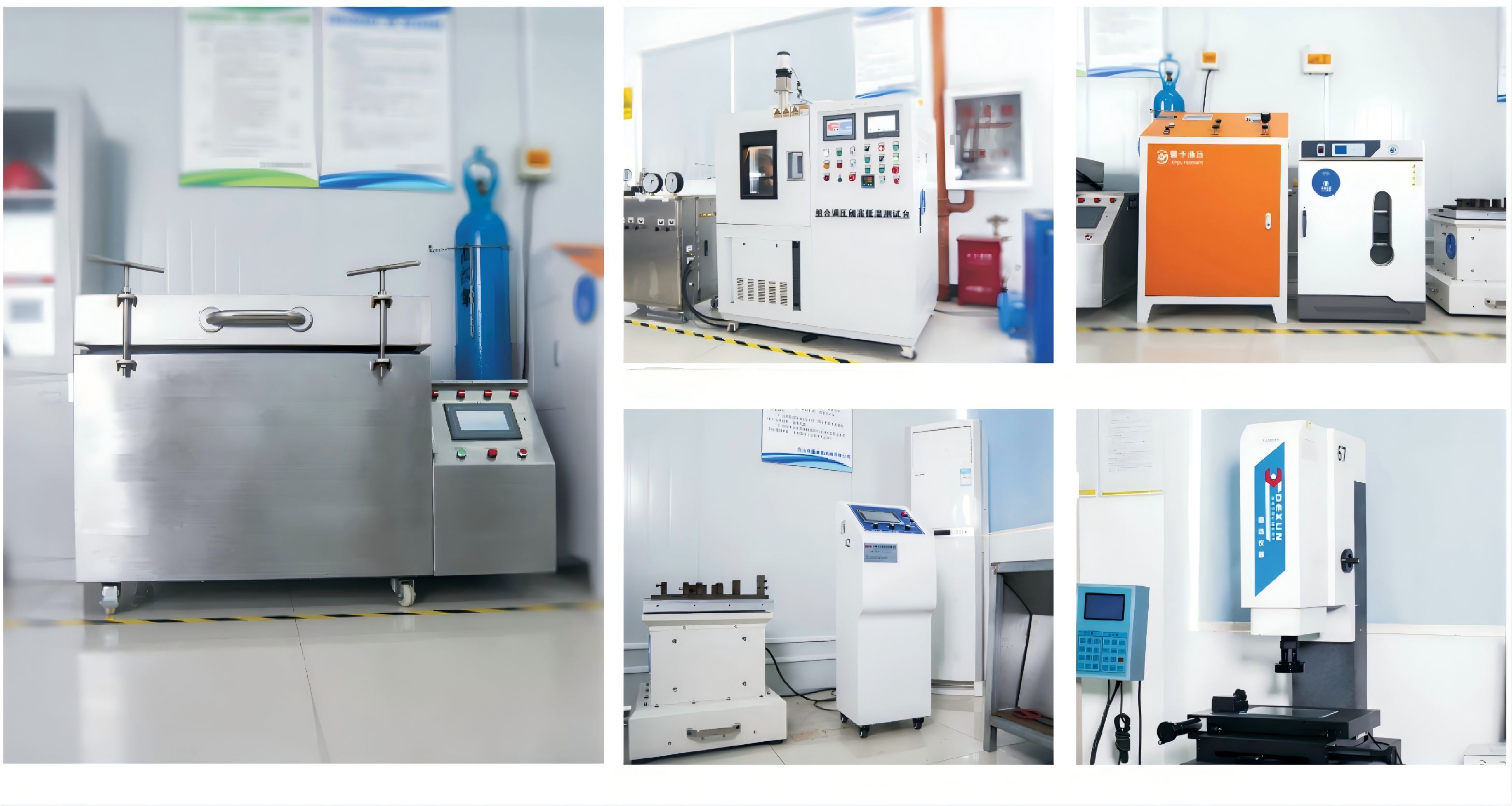
Factory Shoot
1: What do the two 1/2-14NPT auxiliary ports connect to?
A: These two NPT ports are auxiliary access points on the valve body, independent of the main M27×2 inlet/outlet flow path. Typical configurations: (a) one port fitted with a glycerin-filled pressure gauge for local tank pressure verification during commissioning and routine inspection; (b) the other port connected to a remote pressure transducer for telemetry or engine ECU pressure feedback; (c) one port used as a vapor-phase equalization tap during initial cooldown to prevent diaphragm cavity liquid lock. If unused, both ports must be plugged with PTFE-taped brass plugs rated for the full 507 PSIG working pressure; leaving them open will vent tank pressure and disable the pressure-building function.
2. Why is the DYS15F width (W=68 mm) so much narrower than the DYS15FM (W=96 mm)?
A: The 29% reduction in lateral envelope is achieved by radially compressing the upper spring guide and bonnet thread interface without altering the diaphragm effective area or the spring wire diameter. The trade-off is a slightly higher bonnet-to-body thread stress concentration and reduced wrench-access clearance around the locknut. The design assumes that tight-space installations will use a crowfoot wrench or thin-wall socket for locknut adjustment rather than a standard open-end wrench. Flow capacity and pressure control precision are unaffected because these parameters are governed by the disc/seat orifice geometry and the diaphragm area, neither of which changes between the two variants.
3. Can DYS15F and DYS15FM be interchanged on the same tank?
A: Partially. The primary M27×2 inlet and outlet threads are identical, so the valve will physically thread into the same tank ports. However: (a) the DYS15FM's wider body (96 mm) may not fit into a mounting bracket designed around the DYS15F's 68 mm width; (b) if the tank piping relies on the DYS15F's NPT auxiliary ports for gauge or telemetry connections, switching to a DYS15FM will require a separate tee fitting and re-plumbing; (c) the locknut position differs relative to the bonnet centerline due to the different bonnet OD (Φ17 vs Φ14), affecting wrench approach angle. Always verify physical clearance and auxiliary port routing before substituting one variant for the other.
4. Are NPT threads reliable in cryogenic service?
A: Yes, with caveats. NPT's taper-thread self-sealing mechanism relies on thread flank interference and a sealant compound. At cryogenic temperatures, thermal contraction of the male NPT fitting versus the female brass port creates a differential shrinkage effect: the stainless steel male fitting (common for instrumentation) contracts approximately 0.3% linearly from ambient to −196°C, while the brass female port contracts approximately 0.4%. This differential tightens the interference fit, improving seal integrity at cold conditions. However, repeated thermal cycling gradually extrudes the PTFE tape sealant from the thread crests. Best practice: use nickel-filled PTFE tape rated for cryogenic service, apply 2.5–3 wraps with a 1-thread setback from the fitting nose, and torque to the fitting manufacturer's cryogenic derated specification.
5. What is the correct orientation for installing the DYS15F?
A: The DYS15F must be installed with the inlet connected to the tank bottom liquid port and the outlet connected to the vaporizer inlet. The valve body is designed for a 90° flow turn (inlet horizontal, outlet vertical upward). This orientation serves two purposes: (a) gravity-assisted drainage ensures any residual liquid in the outlet passage flows back into the valve body during the closed cycle, preventing freeze-lock of the disc; (b) the vertical outlet presents the lowest flow resistance to the two-phase mixture that can form during initial cooldown. Do not mount the valve with the outlet below the inlet or horizontally—these orientations trap liquid in the diaphragm cavity and cause erratic pressure cycling.
6.Does the narrower body affect the valve's flow capacity or service life?
A: No. The internal flow passage diameter, disc/seat orifice geometry, and poppet stroke are identical between DYS15F and DYS15FM. The narrowing is achieved entirely in the external body casting profile and the bonnet thread shoulder width. Since the seven internal components (springs, disc, diaphragm, sealing element) are the same parts, the cycle life—governed by diaphragm fatigue and PTFE seal wear—is unchanged. The factory test protocol (100% tested per GB/T34530.1) applies identically to both variants. The only durability concern specific to the DYS15F is bonnet thread stress under extreme over-torque of the locknut; this is addressed by the locknut's torque-limiting shoulder design.


 yongy0223@gmail.com
 +86-17693104145
 Lanzhou New Area, Lanzhou City, Gansu Province, on the second floor to the east of New Harbor Road, to the east of Building Materials Road No. 2, to the west of Qilian Mountain Avenue (Jingqi Road)