

 |


loading


DGF15/25
SLDW
| Size: | |
|---|---|
| Availability: | |
| Quantity: | |
| Application Overview
After globe valves, emergency shut-off valves, and check valves, the catalog turns to the fourth product category — strictly speaking, it is not even a valve: DGF15/25 Cryogenic Strainer. In the prefix DGF, G is the new letter, standing for Strainer. This is not a device for shutting off or regulating fluid, but a barrier that protects other valves from particulate damage.
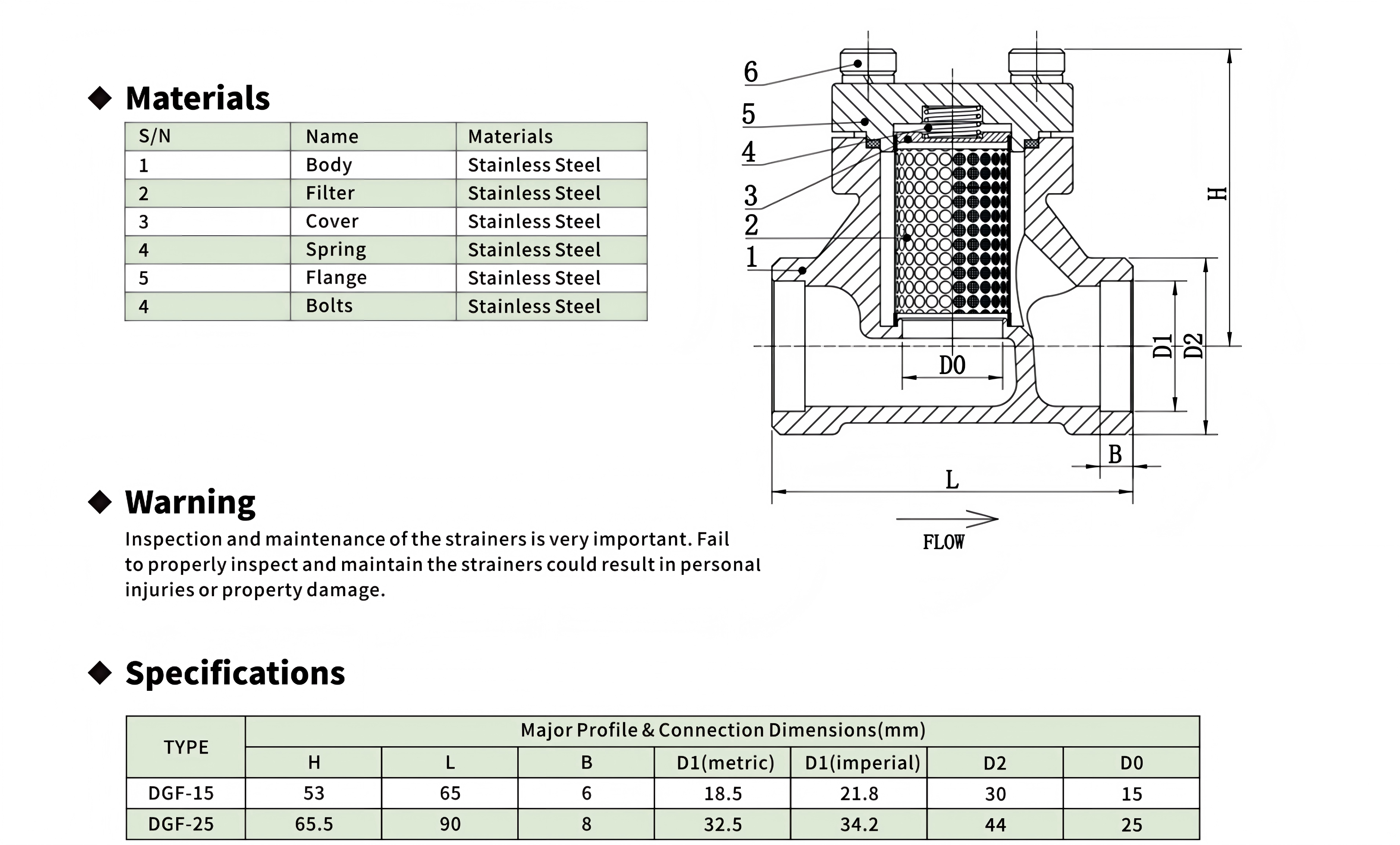
The DGF comes in only two bores — DN15 and DN25. The entire strainer comprises six stainless steel parts: body, filter (dual-drum structure), cover, spring, flange, and bolts. Visually, it is almost a twin of the DH61F-40P check valve — the DGF-15 and DH-15A share identical face-to-face length L (65 mm), identical flange dimensions B/D1/D2 (6 mm / 18.5 / 30), and their overall heights H differ by only 0.5 mm (53 vs 53.5 mm). This is no coincidence: DGF and DH share the same body casting platform. The difference is internal — where the check valve's body cavity houses a spring + plunger + seat assembly, the strainer's body cavity houses a spring + dual-drum filter + cover.
But the DGF carries one design feature absent from the DH: a spring-compensated cover. The cover is not rigidly locked to the body by bolts — the spring is pre-compressed between the cover and flange, providing a buffer stroke for the filter assembly's dimensional expansion/contraction during temperature swings. This design directly addresses a real problem in cryogenic piping: the stainless steel filter cools down before the body (thinner wall, lower thermal mass), and its contraction leads the body's in time — without spring compensation, this time-lagged contraction opens a micron-scale gap between the filter end face and the cover, allowing medium to bypass the filter screen entirely and enter downstream unfiltered.
| Working Principle
Dual-drum filter: not a flat screen, but a fluid-dynamic distributor
The DGF's filter screen is not a simple flat metal mesh — it is "two drums." While the image does not provide an internal cross-section, the description allows reconstruction of the geometry: an outer drum (larger diameter, coarser mesh, structural support + primary interception) and an inner drum (smaller diameter, finer mesh, final filtration) nested coaxially. Medium enters the body from the left, first encounters the outer drum's external surface, passes through the outer drum's mesh into the annular gap between drums, then passes through the inner drum's mesh into the inner drum's central cavity, and exits from the right.
This "drum-annulus-drum" three-stage flow path is superior to a single flat screen for three reasons:
First, filtration area explodes. A drum's surface area far exceeds the area of a flat screen in the same installation envelope. Taking DGF-15 as an example, the filter diameter is constrained by the body's D0=15 mm internal cavity — a flat screen's maximum filtration area would be π × (7.5)² ≈ 1.77 cm²; but a drum (assuming outer drum diameter 12 mm, length 30 mm) has a surface area of π × 12 × 30 ≈ 11.3 cm² — over a six-fold increase. Larger filtration area means lower velocity through the mesh, slower clogging, and longer cleaning intervals.
Second, two-stage filtration divides the clogging risk. The outer drum intercepts large particles (weld spatter, mill scale, ice crystal agglomerates); the inner drum catches fine particles (metal powder, molecular sieve dust). If a single 200-mesh flat screen were used, large and small particles would simultaneously impact the same mesh; large particles would clog the grid's "trunk" positions, causing the effective filtration area to plummet. Dual drums isolate large particles at the outer layer, keeping the inner 200-mesh grid clear.
Third, the annular gap acts as a pressure-equalization buffer. After passing through the outer drum, medium enters the annular gap where velocity is far lower than the jet velocity through the outer drum's mesh — this is a diffuser section: fluid redistributes uniformly in the annulus before passing through the inner drum, avoiding the common single-layer "mesh-jet erosion" where high-velocity jets at localized mesh positions scour downstream, enlarging those mesh openings and degrading filtration precision over time.
Spring-compensated cover: thermal-expansion sealing assurance
The DGF's spring (item 4) plays no role in filtration — it is purely a thermodynamic compensation element. At assembly, the spring is pre-compressed between the cover (item 3) and the flange (item 5) — or possibly between the cover and the filter (item 2) end face (depending on exact construction). Regardless of which face it bears against, the spring's function is consistent: as the filter and body contract at different rates during cooldown, the spring's elastic recovery force continuously pushes the cover against the filter end face, maintaining end-face contact sealing.
Why do the filter and body contract at different rates? Because their thermal time constants differ. The body is a thick-walled casting (B=68 mm flange face is the thin part; the body wall is thicker), with high thermal mass, requiring substantial time to cool from room temperature to −196°C. The filter is a thin-walled stamping/welded assembly (mesh thickness typically 0.51 mm), with minimal thermal mass — it cools to near −196°C almost instantly upon contacting the cryogenic medium.
Assume the DGF-15 is assembled at 20°C ambient — both body and filter at 20°C, spring at its design preload. When −196°C LNG begins flowing through the strainer, the filter contracts to near −196°C within seconds — the linear contraction of stainless steel from 20°C to −196°C is approximately 0.29% (average CTE of 304 SS ≈ 15×10⁻⁶/°C, ΔT=216°C, contraction ≈ 0.32%). If the filter's axial length is 30 mm, contraction is roughly 0.096 mm.
The body requires much longer to cool to the same temperature — during this "time-lag window," the body's axial dimension is unchanged, but the filter is already 0.1 mm shorter. If the cover were rigidly locked, this 0.1 mm gap would be permanent — medium would bypass the filter screen through the gap and flow unfiltered downstream. The spring's role is to absorb this 0.1 mm gap: spring pre-compression is typically designed at 23 mm (far exceeding the 0.1 mm maximum cold-contraction differential); at the onset of contraction, the spring extends by 0.1 mm to fill the gap, and the remaining 1.92.9 mm of preload is still sufficient to hold the cover and maintain sealing. When the body subsequently reaches the same temperature and completes its contraction, the spring returns to near its original preload — seamlessly throughout.*
Stainless steel plunger vs brass disc: check valve and globe valve material divergence
The DH61F-40P's plunger is stainless steel, while the DJ61F-40P globe valve family's discs are uniformly brass. This is not an arbitrary choice — the two valve types subject the closure element to entirely different force regimes.
A globe valve disc is forcibly pressed into the seat by the stem, with the closing torque coming from the handwheel's screw transmission; the force magnitude depends on the operator's hand effort. Brass's advantage here: ① it is softer than stainless steel; even if the operator overtightens, brass yields before the seat, sacrificing the disc to protect the seat (a replaceable disc is easier to service than an integrated body-seat); ② brass-to-stainless stem pairing has superior anti-galling performance compared to stainless-to-stainless.
A check valve plunger is not externally driven — it is lifted by flow pressure, pressed back by the spring. Closing force is spring force + reverse differential pressure, neither excessive nor insufficient. The plunger slides within the bonnet guide bore; stainless-to-stainless self-centering sliding requires precise clearance fit — too loose causes tilt, too tight causes jamming. The DH61F-40P's "self-centering" characteristic indicates the tolerance design between the plunger's cylindrical segment and the bonnet guide bore is sufficiently precise.
Another argument for the stainless plunger: there is no brass-to-stainless threaded pair inside the check valve (the globe valve's stem thread rotates within the bonnet), so no anti-galling requirement exists. And the all-stainless material uniformity eliminates galvanic corrosion risk — if the plunger were brass and the body stainless, in humid or chloride-containing environments, the brass would act as the anode and suffer preferential corrosion.
Dual-track D1: the design intent behind coexisting metric and imperial bores
The DH61F-40P dimension table exhibits a rare feature: D1 is listed with two values — metric and imperial. Taking DH-15A as an example, metric D1=Φ18.5, imperial D1=21.8 mm. These two values do not mean the same body has two different bores — they indicate the body can have its end connections machined to match two pipe outer-diameter standards.
Metric D1 corresponds to ISO metric pipe OD (DN15 → OD 21.3 mm → ID approximately 18.5 mm after subtracting wall thickness); imperial D1 corresponds to ANSI/ASME pipe sizing. The presence of dual-track D1 indicates the DH61F-40P was designed from the outset to accommodate, on the same body casting, different weld-end machining to match metric or imperial piping — common engineering practice for export-oriented products: the valve's installation dimensions (L/B/D2/D0) remain unchanged, only the weld bevel dimensions at the end connections are selected per the customer's pipe standard.
Three different pressure ratings from the same platform: why DGF is 725 PSI, DH is 600 PSI, DJ is 580 PSI?
DGF, DH, and DJ61F-40P (G/D/DN series) share body castings, yet their pressure ratings differ — 725 / 600 / 580 PSI. This ascending sequence seems random but reflects different "pressure-boundary integrity" evaluation criteria. The globe valve (580 PSI) is lowest because its pressure boundary includes a dynamic penetration — the stem through the bonnet, with the stuffing box as a live link in the boundary. Packing wears in service, and the pressure rating must include margin for post-wear sealing. The check valve (600 PSI) is slightly higher because there is no stem penetration — all moving parts are internal, and the pressure boundary is a purely static sealing system of body + bonnet + bolts + gasket. One fewer dynamic sealing link, one more increment of reliability, so the rated pressure can step up. The strainer (725 PSI) is highest because it not only has no penetration and no moving parts, but also no reverse pressure shock — the strainer has no "closed" state; medium always flows unidirectionally. The pressure boundary is purely static pressure-bearing in a single regime across all operating conditions. Moreover, the DGF's flange (item 5) is a standalone piece — unlike the globe/check valve bonnet, the flange needs no guide bore or stem thread machining; its geometry is the simplest, with the fewest stress concentrations, and the pressure rating can be pushed to the casting blank's limit.

|
Factory Shoot


|
Application Video
|
Product parameters


| Data Sheet
|
Comment & FAQ
1: DGF and DH61F-40P have identical installation dimensions — are they interchangeable? Can I replace a check valve with a strainer on the line?
A: Same installation dimensions but entirely different functions — no, not interchangeable. A DGF can physically replace a DH on the line, the bolt holes line up — but they do opposite things: a check valve prevents reverse flow; a strainer prevents no flow in any direction. A typical mistake: using a strainer as a check valve — medium can pass through the strainer in both directions (as long as particles are smaller than the mesh), no check function exists, reverse flow penetrates through the strainer straight into the upstream. The reverse mistake is equally fatal: using a check valve as a strainer — the check valve's plunger and spring cannot intercept any particles smaller than the seat bore; downstream valves (especially the globe valve's PCTFE seat) will be scored by particles within a short time. The correct configuration: DGF immediately upstream of DH — medium first filtered (particles removed), then check-valved (backflow prevented). The two in series on the line; their identical L dimensions mean the strainer can be added without altering the pipe spacing — add short pipe stubs on both ends of the existing globe/check valve node, insert the DGF + DH series pair in between.
2: How to tell when the filter needs cleaning? At what differential pressure should I open it?
A: The most reliable method: install pressure gauges (or a DP transmitter) upstream and downstream of the strainer. A clean filter's pressure drop is typically in the 0.52 PSI range (100 mesh) — depending on flow rate and medium viscosity. When the DP rises to 35× the clean pressure drop (i.e., 1.5~10 PSI), it's time to clean. Without gauges, the rule of thumb: during normal LNG loading/unloading, if the time to load/unload the same quantity of LNG is noticeably extended (e.g., from 30 minutes to 40 minutes) and the pump is confirmed fine — the filter is very likely clogged. Never wait until "flow suddenly drops to near zero" to open it — by then, the filter has been compacted into a solid cake, and the inner drum may already be deformed or locally ruptured under excessive DP. Once the filter ruptures, all intercepted particles flush downstream into the valves in one massive release — causing worse damage than having no strainer at all (because particles, once collected, are released in a concentrated burst, with impact density far exceeding normal medium-carrying levels).
3 : DGF only comes in DN15 and DN25 — my line is DN32. What do I do? Why is there no DGF-32?
A: DGF's bore coverage is constrained by two factors: ① it shares the DH61F-40P body platform — DH has DN15~32 across four bores, so DGF could technically go to DN32 (DH-32A L=105 vs DGF-25 L=90, a 15 mm difference); ② but DN32's D0=32 mm gives the internal dual-drum filter nearly 60% more radial space than DN25 (D0=25 mm) — larger filter diameter, no filtration area problem. The absence of a DGF-32 model is likely commercial rather than technical — DN32 market demand is insufficient to support standalone product certification and inventory. If your line is DN32, three solutions: Option 1 (recommended): Use DGF-25 + reducer (DN32→DN25) to neck down. The filter experiences elevated velocity in the reduced section — but unless the initial velocity is already at its limit, this speed increase won't cause easy clogging (in fact, higher velocity improves inertial particle separation, benefiting large-particle capture). Option 2: Install only a DH-32A check valve on the DN32 line (no strainer), and install a larger-bore strainer on the upstream DN50 main header. Option 3: Custom-order DGF-32 from the manufacturer — based on DH-32A body casting, machine the filter mounting cavity internally. Technically feasible but requires separate quotation and minimum order quantity.
4: The spring-compensated cover design — won't the spring force decay over time? Does it still hold after prolonged cryogenic cycling?
A: Stress relaxation is the fate of all elastic elements, but the DGF spring's working conditions favor it. Spring stress relaxation rate is governed by three factors: temperature, initial stress, and cycle count. The DGF spring operates between −196°C and +85°C — stainless steel's dislocation motion is suppressed at low temperature, and stress relaxation rate is far lower than at room temperature; the +85°C high end is also insufficient to activate significant creep in austenitic stainless steel (304 SS creep temperature threshold is typically above 400°C). Regarding initial stress, the spring preload only needs to compensate for approximately 0.1 mm cold-contraction differential — this stroke is tiny, the spring's initial stress is far below its yield strength (typically 2030% of yield, preload stress), in the low-stress-relaxation regime. Cycle count also matters — each line thermal cycle (ambient → −196°C → ambient) is one load-unload cycle. But the DGF spring's strain change in one cycle is only a tiny fraction (0.1 mm / 23 mm ≈ 3~5%); this is not a fatigue problem — the spring will not approach high-cycle fatigue conditions over its entire service life. Conservative estimate: the DGF spring will not need replacement over a 20-year normal service life. If replacement is eventually needed, spring replacement is even simpler than filter cleaning — open the flange, remove the old spring, insert the new spring, re-tighten the flange — less than 10 minutes total.
5: DGF and DH61F-40P share the body — even the bolt holes are identical? Can I remove the check valve bonnet and install the strainer flange and filter directly?
A: Shared body casting — same blank. But internal machining differs: the check valve's body cavity is machined with a seat-ring mounting groove and plunger guide bore; the strainer's body cavity is machined with filter-locating stops and cover seating faces. The two follow different machining routes post-casting; the finished bodies are not interchangeable. Regarding sub-assembly interchangeability: technically possible — if you are willing to re-machine the body cavity. But this is unrealistic at shop level: the original seat-ring mounting groove must be ground off and a new filter mounting cavity bored — the precision requirement makes this near-impossible outside the OEM. The more practical approach: procure DGF and DH as two separate complete valves — one for filtration, one for backflow prevention, used in series.

 yongy0223@gmail.com
 +86-17693104145
 Lanzhou New Area, Lanzhou City, Gansu Province, on the second floor to the east of New Harbor Road, to the east of Building Materials Road No. 2, to the west of Qilian Mountain Avenue (Jingqi Road)


