

 |


loading


DYJ15A
SLDW
| Size: | |
|---|---|
| Availability: | |
| Quantity: | |
| Product Overview
The DYJ15A occupies a position in the DJ/DY valve family that no previous document has covered: it is a pressure-reducing regulator—a device that takes gas at high inlet pressure from a cryogenic tank vapor space and delivers it at a stable, reduced outlet pressure to downstream equipment. The prefix "DYJ" (where "J" denotes , pressure reduction) signals this functional departure from the DYS (pressure building) and DYS25A lineages. The DYJ15A controls the gas supply side of the tank system, whereas DYS regulators control the liquid-to-vapor pressure-building loop and the DYS25A economizer controls the vapor-space pressure ceiling.
The economic logic is straightforward but often overlooked in tank station design. A cryogenic tank at service pressure (100–500 PSIG depending on vessel MAWP) contains gas at pressures far exceeding what most downstream equipment requires. Welding gas manifolds, laboratory gas distribution headers, and cryogenic filling stations typically need 50–80 PSIG. If the tank feeds these consumers directly without pressure reduction, two things happen: first, the flow control valves at each point-of-use must absorb the full pressure drop, which accelerates seat erosion and leads to maintenance-intensive operation; second, any downstream demand fluctuation is transmitted directly back to the tank vapor space, causing pressure oscillations that can trigger the safety relief valve. The DYJ15A eliminates both problems by inserting a regulated pressure step between the tank and the distribution header, delivering a constant outlet pressure regardless of whether the tank is at 100 PSIG or 500 PSIG.
The physical design reflects this role. H = 125 mm total height and W2 = Φ76 mm flange diameter make the DYJ15A the most compact regulator in the entire DJ/DY catalog—less than half the height of a DYS20A (255 mm) and less than half the length of a DYS25A (270 mm). This miniaturization is possible because a pressure-reducing regulator handles gas, not liquid; the orifice diameter required to pass the mass flow of tank boil-off vapor is much smaller than the liquid orifice needed for a pressure-building vaporizer feed. The 2-M NPT-1/2 threaded ports are standard tapered pipe threads compatible with off-the-shelf cryogenic piping fittings—no custom swivel nuts, no special tube-end preparation.
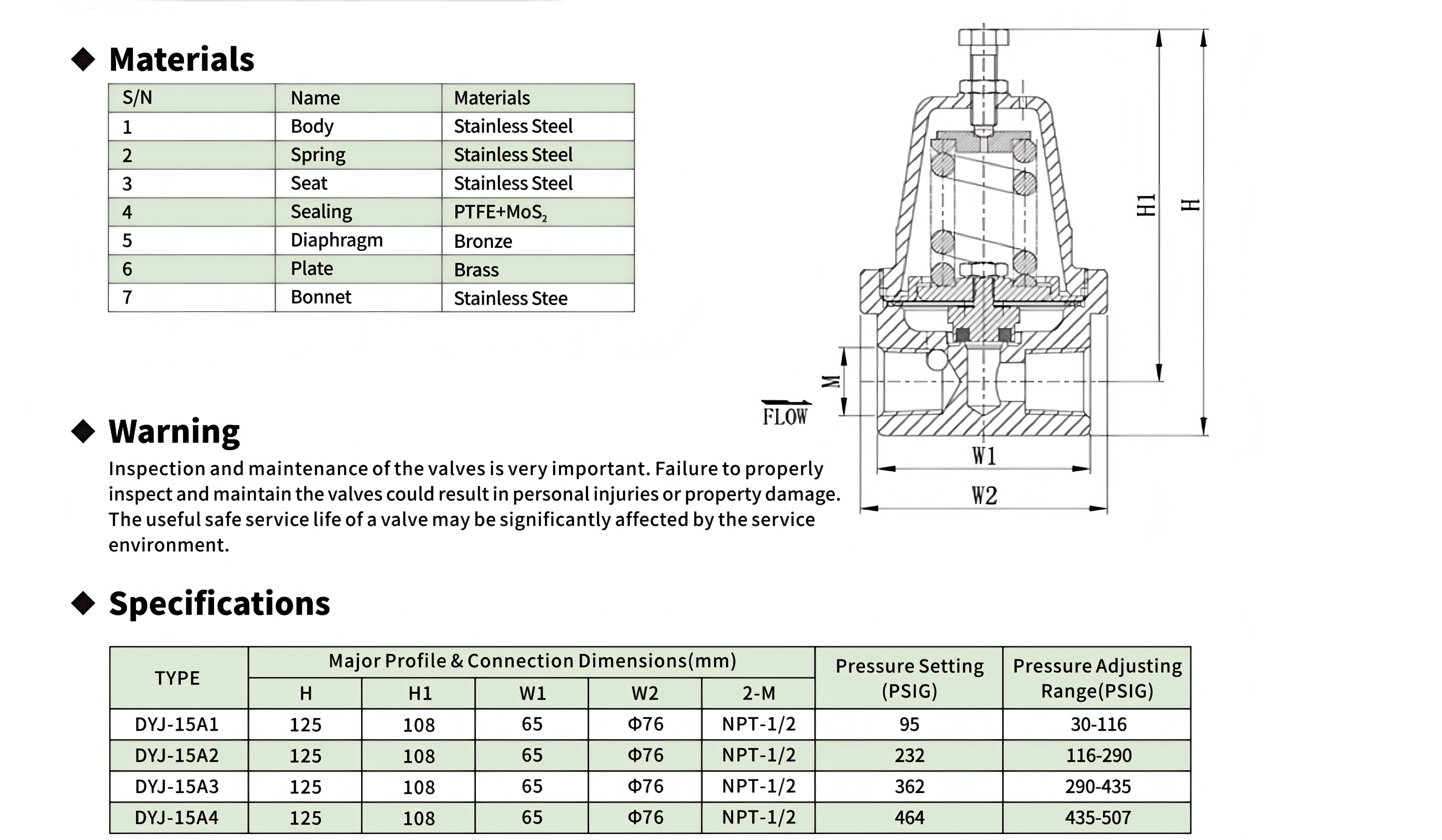
The component count is seven: 304SS body (1), 304SS spring (2), 304SS seat (3), PTFE+MoS₂ composite sealing element (4), bronze diaphragm (5), brass plate (6), and 304SS bonnet (7). This is the lowest component count of any DJ/DY regulator—the DYS15 series has seven but adds separate auxiliary port fittings, and the DYS25A has fourteen. The PTFE+MoS₂ sealing material (component 4) is noteworthy: molybdenum disulfide is a lamellar solid lubricant with a coefficient of friction approximately 0.04–0.08 in dry nitrogen environments, roughly half that of unfilled PTFE. When embedded in a PTFE matrix at 5–15% by weight, MoS₂ reduces the seat's "stick-slip" behavior during partial-lift throttling—the phenomenon where the seal alternately grips and releases the seat, producing downstream pressure pulsation. This is especially important in a pressure-reducing regulator where the seat is continuously modulating near the set point during normal operation, unlike a safety or economizer valve that is either fully closed or fully open most of the time.
The four sub-variants (A1 through A4) provide what is effectively a four-band progressive spring matrix: A1 (30–116 PSIG), A2 (116–290 PSIG), A3 (290–435 PSIG), and A4 (435–507 PSIG). The presence of a fourth band—where DYS regulators typically offer three—is driven by the physics of downstream pressure regulation. In a pressure-reducing regulator, the proportion of spring force to controlled pressure becomes increasingly nonlinear at the upper end of each range because the effective diaphragm area changes as the diaphragm deflects (a phenomenon called "diaphragm area effect" or "effective area droop"). By adding a fourth spring band, each band covers roughly 150–200 PSIG instead of 250–350 PSIG, and the droop within any single band is held to 3–5% rather than the 6–10% that a wider three-band scheme would produce. The set-point pressures (95, 232, 362, 464 PSIG) are not the midpoint of each range but the factory calibration point corresponding to a typical tank MAWP less the 10–15 PSIG economizer offset—the same logic used in the DYS25A range selection.
All four pressure variants share the same external dimensions: H = 125, H1 = 108, W1 = 65, W2 = Φ76. The "same compact size" claim in the product sheet is not a marketing simplification—it is a constraint of the single body casting (component 1) and single bonnet (component 7) shared across all four variants. The four different pressure ranges are achieved entirely by changing the spring wire diameter and coil count within the same spring cavity, and by adjusting the seat orifice diameter (which is machined, not cast, and thus variable without changing tooling). This is a manufacturing optimization that reduces SKU count on the assembly line while preserving full-range coverage for the end user.
| Working Principle
The DYJ15A is a downstream-pressure-sensing, spring-loaded, direct-acting pressure-reducing regulator. Unlike the DYS pressure-building regulators (which sense tank vapor-space pressure and open when it drops below a set point) and the DYS25A back-pressure economizer (which senses tank pressure and opens when it rises above a set point), the DYJ15A senses outlet pressure and modulates the valve opening to hold that outlet pressure constant—regardless of inlet pressure fluctuations.
Operational Cycle in Detail:
Static (No-Flow) Condition:No gas is being drawn by downstream equipment. The outlet cavity pressure equals the regulator's set point. The diaphragm (component 5) is in equilibrium—the downward force of the spring (2) plus atmospheric pressure on the diaphragm's upper face exactly balances the upward force of the outlet pressure acting on the diaphragm's lower face. The seat sealing element (4) is lightly closed against the seat (3), preventing gas flow from the high-pressure inlet side to the low-pressure outlet side.
Flow Demand Begins: A downstream valve opens, and gas begins to flow out of the outlet cavity. Outlet pressure drops by 1–3 PSIG below the set point. The force balance on the diaphragm is disrupted: the downward spring-plus-atmosphere force now exceeds the reduced upward outlet-pressure force. The diaphragm deflects downward.
Valve Opening: The downward diaphragm deflection is transmitted through the brass plate (6) to the valve stem. The stem pushes the PTFE+MoS₂ sealing element (4) away from its mating stainless steel seat (3), creating an annular flow passage. High-pressure gas from the inlet side flows through this gap into the outlet cavity, and from there to the downstream equipment. The opening is proportional to the pressure deficit—a small deficit produces a small opening (partial lift), a large deficit produces a larger opening.
Steady-State Delivery: Once the flow of gas into the outlet cavity (through the open seat) equals the flow of gas out of the outlet cavity (to the downstream load), the outlet pressure stabilizes at a value 2–5% below the no-flow set point. This offset—called "droop" or "offset" in regulator terminology—is the inherent characteristic of all direct-acting spring-loaded regulators. The DYJ15A's four-band spring matrix limits droop to 3–5% within each band, compared to 6–10% if the same total range (30–507 PSIG) were covered by only three springs.
Flow Stops / Inlet Pressure Rises: When downstream demand ceases or the inlet pressure rises (e.g., tank heats up due to ambient temperature increase), the outlet pressure momentarily exceeds the set point. The upward force on the diaphragm exceeds the spring-plus-atmosphere downward force. The diaphragm deflects upward, the stem retracts, and the sealing element (4) closes against the seat (3)—or, more commonly in modulated operation, moves closer to the seat to reduce the flow area. The regulator thus maintains outlet pressure to within its droop band regardless of inlet pressure or downstream demand changes.
The MoS₂ Rationale:
The PTFE+MoS₂ composite sealing element (component 4) is the most materially significant feature of the DYJ15A. In a pressure-reducing regulator that modulates continuously near the set point, the seat experiences thousands of small-amplitude motions per day—a regime called "fretting" in tribology. Unfilled PTFE, despite its low friction coefficient (~0.08–0.12), exhibits a well-documented stick-slip behavior at very low sliding velocities: the seal momentarily adheres to the seat surface, then abruptly releases, producing a 2–5 PSIG pressure pulse in the outlet stream. Over weeks of continuous service, these pulses accumulate as fatigue cycles on downstream diaphragm-operated equipment.
Molybdenum disulfide (MoS₂) is a transition-metal dichalcogenide with a hexagonal layered crystal structure. The layers are bonded by weak van der Waals forces that shear easily under load, providing a solid lubricant film that is effective even in high-vacuum and cryogenic environments where liquid lubricants would freeze or evaporate. When compounded into PTFE at 5–15 wt%, MoS₂ platelets align parallel to the sliding direction during the first few operating cycles, forming a transfer film on the stainless steel seat surface. The resulting MoS₂-on-MoS₂ sliding interface has a friction coefficient of 0.04–0.08 in dry nitrogen at −196°C, and—critically—exhibits near-zero stick-slip amplitude because the shear occurs within the MoS₂ basal planes rather than at the PTFE-stainless interface.
Why Four Ranges:
The move from three bands (typical of DYS regulators) to four bands for the DYJ15A is not arbitrary. A pressure-reducing regulator's droop—the difference between no-flow set pressure and full-flow delivered pressure—increases approximately linearly with the span of each spring range. Narrowing each band from ~170 PSIG (three-band scheme: 30–116, 116–290, 290–507) to ~125–145 PSIG (four-band scheme) reduces the per-band droop from ~8% to ~4%. For the end user, this means that a DYJ-15A2 set at 200 PSIG will deliver 192–196 PSIG at full flow rather than 184–190 PSIG—a difference that may eliminate the need for a secondary trim regulator at the point of use

|
Factory Shoot


|
Application Video
|
Product parameters


| Data Sheet
|
Comment & FAQ
1: What is the fundamental difference between DYJ15A, DYS regulators, and DYS25A economizer?
A: All three share the "economizer" nomenclature because they all prevent product loss via the safety relief valve, but they do so at completely different points in the tank system. The DYS series (e.g., DYS15B, DYS20A) are pressure-building regulators: they sense tank gas-space pressure, and when it drops below a lower threshold, they open the liquid PB circuit to a vaporizer to actively raise tank pressure. The DYS25A is a back-pressure economizer: it senses tank pressure and, when it rises above an upper threshold, bleeds vapor directly to the downstream header to prevent the SRV from lifting. The DYJ15A is a pressure-reducing regulator: it sits between the tank and the downstream distribution system, reducing whatever tank pressure exists (inlet) to a constant, lower pressure (outlet) that equipment can safely consume. All three work together in a well-designed large tank station: DYS maintains the lower pressure bound, DYS25A caps the upper bound, and DYJ15A isolates the supply side from tank pressure excursions.
2. Why is the DYJ15A called a "cryogenic economizer" when it's a pressure reducer?
A: The term "economizer" in cryogenic tank terminology refers to any device whose primary economic justification is reducing product loss through the safety relief valve. The DYJ15A qualifies because it enables the tank to be stored at a higher pressure (storing more thermal energy in the liquid, which delays the next pressure-building cycle) while delivering gas to equipment at a lower, usable pressure. Without the DYJ15A, the operator would either need to vent the tank to a lower pressure before supplying equipment (wasting product through the SRV) or supply equipment at full tank pressure (causing flow-control problems). The DYJ15A "economizes" by decoupling storage pressure from delivery pressure—two variables that are inherently linked in a direct tank-to-equipment connection.
3. Why four progressive ranges instead of the three used in DYS regulators?
A: The physics answer is "diaphragm area droop." A pressure-reducing regulator's actual delivered pressure at full flow is always lower than its no-flow set pressure because the diaphragm must deflect through a finite distance to open the valve, and the spring force changes linearly with deflection while the downstream demand is nonlinear. The wider the pressure range covered by a single spring, the larger the percentage droop at the upper end of the range. Covering 30–507 PSIG in three bands produces ~8% droop at the top of each band; covering it in four bands reduces droop to ~4%. The practical answer is that gas supply regulation to precision equipment (gas chromatographs, laser cutting optics purge systems, semiconductor process gas panels) demands tighter outlet pressure stability than tank pressure building, which is a bulk control function.
4. What does the PTFE+MoS₂ seat sealing offer over standard PTFE?
A: Molybdenum disulfide is a solid lubricant that works at cryogenic temperatures where all liquid lubricants are frozen solid. The key benefit in the DYJ15A is elimination of the stick-slip phenomenon that occurs when an unfilled PTFE seat modulates at very low sliding velocities near the set point. Stick-slip causes downstream pressure pulsation at 0.5–5 Hz, which downstream equipment "sees" as supply pressure instability. The MoS₂ transfer film that forms on the stainless steel seat during the first few hours of operation creates a self-lubricating interface where shear occurs within the MoS₂ crystal basal planes rather than at the PTFE-metal boundary. The friction coefficient drops from ~0.10 (PTFE on stainless, dry N₂, −196°C) to ~0.05 (PTFE+MoS₂ on MoS₂ transfer film), and the stick-slip amplitude drops from 2–5 PSIG peak-to-peak to less than 0.5 PSIG.
5. How can all four pressure variants share the same external dimensions?
A: The four variants (A1 through A4) use a single body casting and a single bonnet, with the only differences being the spring (wire diameter and active coil count) and the seat orifice diameter. The spring cavity inside the bonnet is large enough to accommodate the heaviest spring (A4, with the largest wire diameter), and the body's internal flow passages are machined with different orifice diameters for each range. This is purely a manufacturing optimization—it means the foundry produces one body pattern, one bonnet pattern, and assembly uses modular spring/seating kits to configure the final pressure range. The trade-off is that the A1 spring operates in a cavity optimized for the A4 spring, meaning the A1 spring's lateral buckling safety factor is higher than strictly necessary (the cavity is wider than the A1 spring needs), but this has no functional penalty.
6. What is the correct flow direction through the DYJ15A, and does orientation matter?
A: The flow direction is from the high-pressure port (inlet, connected to the tank vapor space or high-pressure gas header) to the low-pressure port (outlet, connected to the downstream distribution system). The body casting should have a FLOW arrow marking. Orientation matters in three ways: (1) the regulator must be installed with the flow arrow pointing in the direction of intended gas travel—reverse installation will expose the diaphragm to inlet pressure on the wrong side and may rupture it; (2) the bonnet should be oriented vertically upward to prevent condensate or ice accumulation from entering the spring chamber through the adjusting screw threads; (3) the NPT-1/2 threads require PTFE tape or a cryogenic-compatible thread sealant (nickel-based anti-seize for oxygen service, not copper-based) applied to the male threads only—never to the female ports on the body, as excess sealant can migrate into the seat orifice.

 yongy0223@gmail.com
 +86-17693104145
 Lanzhou New Area, Lanzhou City, Gansu Province, on the second floor to the east of New Harbor Road, to the east of Building Materials Road No. 2, to the west of Qilian Mountain Avenue (Jingqi Road)


