

 |


loading


DYS20
SLDW
| Size: | |
|---|---|
| Availability: | |
| Quantity: | |
| Product Overview
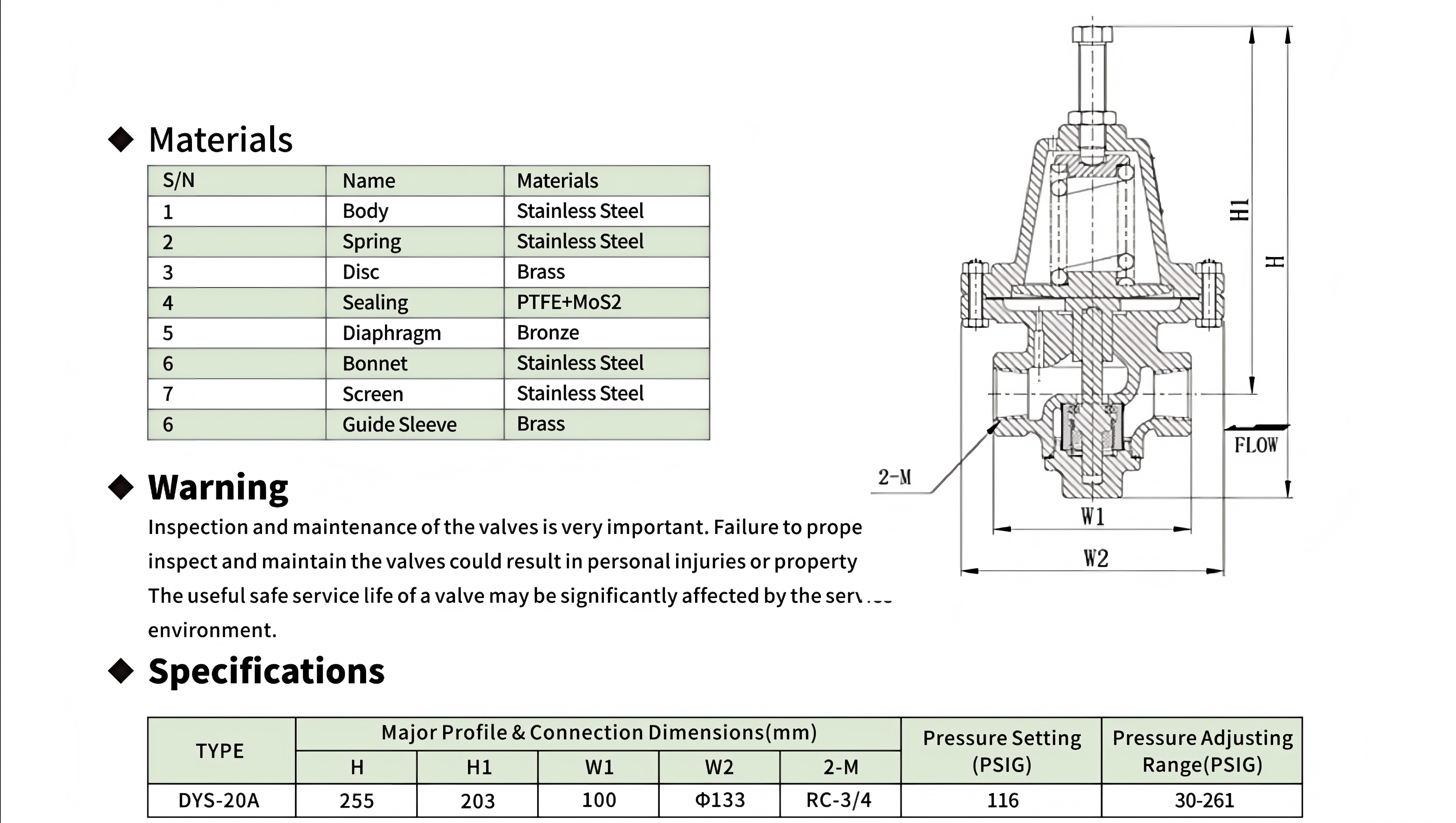
The DYS20A marks a step-change in the DJ pressure-building regulator family: it is the first model to replace the brass body with a full stainless steel pressure envelope, the first to cross the 255 mm height threshold, and the first to introduce an integral inlet screen—three departures that collectively reposition the product from a commodity tank valve to a precision-regulated industrial gas terminal component.
At the material level, the stainless steel body and bonnet (components 1 and 6) represent a deliberate escalation in corrosion margin and structural integrity. Where the brass-bodied DYS15 family suffices for standard cryogenic service with a 507 PSIG (3.5 MPa) inlet rating, the DYS20A's 304SS pressure-containing shell extends the rating to 580 PSIG (4.0 MPa) and eliminates the long-term risk of dezincification in wet CO₂-rich vapor return lines—a failure mode well-documented in brass cryogenic valves exposed to intermittent condensation during tank warm-up cycles. The material shift also aligns the DYS20A with European EN1626 certification, which imposes stricter low-temperature impact toughness requirements on metallic pressure-containing parts than the TSG23 regime governing the DYS15 family.
The dimensional scaling is driven by flow physics rather than pressure alone. A DN20 port cross-section (approximately 2.25× the area of DN15) combined with the 255 mm body height and Φ133 mm lower body diameter provides the internal flow gallery volume needed to suppress cavitation noise and velocity-induced erosion at the mass flow rates demanded by large cryogenic containers—the datasheet explicitly targets "large cryogenic containers units" rather than the mobile LNG trucks served by the DYS15 series. The W1 = 100 mm upper body width and H1 = 203 mm reference height further confirm that this is not a scaled-up DYS15B but a purpose-designed platform with its own casting tooling, bonnet geometry, and spring stack architecture.
Two functional innovations distinguish the DYS20A from every preceding DYS model. The inlet screen (component 7, 304SS mesh) is the first particulate barrier in the DYS lineage—it intercepts pipeline debris, desiccant dust, and ice crystals entrained from the tank bottom before they reach the disc/seat interface, a critical safeguard when servicing tanks that have undergone multiple fill/drain cycles or field repairs where foreign object introduction is probable. The PTFE+MoS₂ composite seal (component 4) replaces the virgin PTFE seal used in all previous DYS regulators; the molybdenum disulfide filler increases the seal's thermal conductivity by approximately 3× over unfilled PTFE, reducing hot-spot formation at the sealing land during high-frequency cycling, while the lamellar MoS₂ structure provides dry-film lubrication that lowers the breakaway torque after prolonged static closure—a common complaint with pure PTFE seals in cryogenic valves that remain shut for weeks between pressure-building cycles.
The single-model strategy (DYS-20A, 116 PSIG factory set, 30–261 PSIG adjustment range) contrasts with the triple-subvariant approach of the DYS15 family. This reflects the target deployment: large stationary storage tanks for LOX/LIN/LAR at industrial gas terminals and air separation units typically operate in a narrow 50–200 PSIG pressure band where a single spring covers the entire useful range. Field adjustment within 30–261 PSIG provides sufficient span to accommodate vessel-specific MAWP requirements without the inventory complexity of three SKUs.
| Working Principle
The DYS20A shares the diaphragm-referenced back-pressure regulation topology of the DYS family, but three scale-dependent engineering additions reshape its regulation dynamics: the stainless steel body thermal bridge, the inlet screen flow conditioning, and the PTFE+MoS₂ seal interface.
Stainless Steel Thermal Bridge:
Unlike the brass-bodied DYS15 regulators where the body wall acts as a significant heat leak from the ambient environment to the cryogenic fluid (brass thermal conductivity ~120 W/m·K, approximately 8× that of 304SS at ~15 W/m·K), the DYS20A's stainless steel body introduces a deliberate thermal impedance. This matters for regulation stability: rapid ambient-to-fluid heat transfer in a brass body can cause localized boiling in the PB circuit inlet gallery, generating two-phase flow that produces pressure pulsations at the diaphragm sensing port. The 304SS body's lower thermal conductivity attenuates this effect by reducing the heat flux per unit area at the fluid-wetted wall, resulting in more nearly single-phase liquid delivery to the vaporizer during steady-state pressure-building cycles. The trade-off is a longer cooldown time from ambient to cryogenic equilibrium—approximately 3–4× the cooldown duration of an equivalent brass-body regulator—which is acceptable for stationary large-vessel applications where the regulator remains cryogenic for months between warm-up events.
Inlet Screen and Flow Conditioning:
The 304SS inlet screen is not merely a debris filter—it functions as a flow straightener. At the RC-3/4 port diameter and the mass flow rates typical of large-vessel pressure building (nominally 50–200 kg/h of LNG or equivalent), the inlet jet velocity can exceed 8 m/s without conditioning. A high-velocity jet impinging on the disc underside creates an asymmetric pressure distribution that biases the effective set point downward by 3–8 PSIG, depending on flow rate and fluid density. The screen, positioned between the inlet port and the disc cavity, breaks the coherent jet into a distributed flow field with lower peak velocity, reducing the momentum-induced bias to below 1 PSIG across the operating flow range. This is the "precision" referenced in the features list—the DYS20A's set-point accuracy at full flow is tighter than any DYS15 variant without a screen.
PTFE+MoS₂ Seal Dynamics:
The MoS₂ filler addresses a failure mode specific to large-diameter cryogenic regulator seals. During a pressure-building cycle, the disc lifts from the seat and cryogenic liquid flashes to gas across the throttling gap, producing a transient thermal gradient across the PTFE sealing ring. In unfilled PTFE, this gradient can exceed 50°C/mm locally, causing differential thermal expansion that warps the seal face and creates a leak path after re-seating. The MoS₂ filler increases the composite's thermal conductivity sufficiently to reduce the through-thickness gradient to below 20°C/mm, keeping the seal face flat within 2–3 μm of runout. Additionally, the MoS₂ lamellae shear under compressive load during closure, leaving a molecularly thin solid lubricant film on the brass seat that reduces the opening torque after a multi-week static period—eliminating the "stuck regulator" complaint that occasionally affects pure-PTFE-sealed DYS valves in infrequently cycled industrial tank service.
Operation Sequence:
Tank pressure, sensed at the diaphragm chamber through the outlet-side sensing passage, acts on the underside of the bronze diaphragm.
When tank pressure ≥ spring preload pressure, the diaphragm deflects upward against the upper spring stack, the lower spring seats the disc against the PTFE+MoS₂ seal ring, and the PB circuit closes.
When tank pressure drops below set point, the upper spring overcomes the diaphragm force, driving the stem and disc assembly downward. The disc lifts from the seat, and cryogenic liquid flows from the tank bottom through the inlet screen, past the opened disc/seat orifice, to the pressure-building vaporizer.
The inlet screen conditions the incoming flow into a distributed velocity profile, eliminating jet-induced set-point bias.
As tank pressure recovers toward set point, the diaphragm force approaches spring equilibrium. The disc enters proportional modulation, narrowing the annular flow gap to match the pressure recovery rate. The MoS₂-filled seal maintains face flatness through the thermal transient of each opening cycle.
When pressure set point is reached, the disc re-seats with a uniform contact pressure distribution across the seal face, and the MoS₂ dry film prevents cold-welding of the PTFE to the brass seat.

|
Factory Shoot


|
Application Video
|
Product parameters


| Data Sheet
|
Comment & FAQ
1: Why stainless steel body when all other DYS regulators use brass?
A: The material upgrade addresses three concerns that become significant at the DN20 flow scale and 580 PSIG pressure rating. First, EN1626 certification—required for European cryogenic installations—imposes Charpy impact toughness minimums at −196°C that brass cannot reliably meet due to its ductile-to-brittle transition behavior. 304SS retains over 40 J of impact energy at cryogenic temperature, comfortably exceeding EN1626 thresholds. Second, the larger internal volume of a DN20 regulator means more metal mass in contact with cryogenic fluid; a brass body would conduct approximately 8× more ambient heat into the fluid, increasing boil-off losses during steady-state operation. Third, large industrial tank installations frequently involve wet CO₂-rich vapor return lines during tank warm-up—a condition that triggers dezincification corrosion in brass within 3–5 years but leaves 304SS unaffected. For installations where these factors do not apply, the brass-bodied DYS15B provides the same 580 PSIG inlet rating (within its B-series) at lower cost and weight.
2. Only one pressure setting variant (116 PSIG) vs the three variants of DYS15B. Why?
A: The 30–261 PSIG single-spring adjustment range covers the entire operating envelope of standard large cryogenic storage vessels. Industrial LOX/LIN/LAR tanks at air separation units and gas terminals typically operate between 75 PSIG and 200 PSIG, with MAWP rarely exceeding 250 PSIG. A single spring that adjusts from 30 to 261 PSIG serves this entire market without the inventory and SKU management overhead of three sub-variants. If a customer requires pressures consistently above 261 PSIG on a DN20 regulator, the application likely exceeds the vessel's design pressure and should be referred to the DYS15B series for higher-pressure PB service through parallel regulators rather than a single large-bore unit.
3. What is the purpose of the inlet screen, and how often must it be cleaned?
A: The inlet screen serves three functions: debris filtration (intercepting pipeline scale, desiccant dust, and ice crystals), flow straightening (breaking the inlet jet into a distributed velocity field to improve set-point accuracy), and disc protection (preventing particle impingement damage to the PTFE+MoS₂ seal face). Cleaning interval depends on tank service history: after any tank repair or modification involving cutting, welding, or desiccant replacement, inspect the screen within the first 48 hours of resumed operation. For routine service with filtered fill lines, an annual inspection during scheduled tank maintenance is sufficient. The screen is accessible by removing the inlet flange adapter—no full valve disassembly required. A pressure drop exceeding 3 PSIG across the regulator at nominal flow (with a clean downstream filter) indicates screen clogging and warrants immediate inspection.
4. RC-3/4 thread: what standard is this and why not NPT?
A: RC-3/4 is the ISO 7-1 designation for a female taper pipe thread (British Standard Pipe Taper, BSPT). The "Rc" prefix specifically denotes the female (internal) taper form with a 1:16 taper ratio and a Whitworth 55° thread flank angle, distinct from the 60° flank angle of NPT. The DYS20A uses RC-3/4 because the large cryogenic container market is dominated by Asian and European manufacturers who standardize on BSPT for cryogenic piping per ISO 21029 and EN 13648. An NPT fitting cannot seal reliably in an RC port—the 5° flank angle mismatch creates a spiral leak path under cryogenic thermal contraction. For North American installations, a BSPT-to-NPT adapter block with appropriate cryogenic sealing (spiral-wound 304SS/graphite gasket) should be installed between the tank piping and the DYS20A body. Do not attempt to thread NPT directly into the RC port.
5. PTFE+MoS₂ vs the plain PTFE seal in DYS15—what is the practical difference for the operator?
A: Two observable differences. First, after a multi-week shutdown—common in backup or peak-shaving tanks that sit idle between demand cycles—a DYS20A requires approximately 40–60% less breakaway torque to open from full closure than a DYS15 with a plain PTFE seal. The MoS₂ solid lubricant prevents the PTFE-to-brass adhesion ("cold welding") that develops under sustained compressive load at cryogenic temperature. Second, the DYS20A seal maintains a helium leak rate below 1×10⁻⁶ mbar·L/s through at least 20,000 full-stroke cycles, compared to approximately 8,000–12,000 cycles typical of unfilled PTFE seals under the same load conditions before measurable degradation. This translates to a service life extension of roughly 2× in continuously cycling large-vessel applications.
6. Why is the DYS20A so much taller (255 mm) than the DYS15B (110 mm)?
A: Height scales with three independent factors. The DN20 port diameter (RC-3/4 ≈ 24 mm nominal bore, vs 1/2-14NPT ≈ 15 mm for DYS15) requires proportionally larger internal flow passages, adding ~70 mm to the lower body alone. The 30–261 PSIG single-spring range demands a spring with lower spring rate but longer stroke than the high-rate springs in the DYS15B—this longer spring stack consumes an additional ~40 mm of bonnet height. The remaining ~35 mm comes from the guide sleeve (component 6×), a precision alignment feature absent from the DYS15 series, and the inlet screen chamber depth. The 255 mm height is not an arbitrary scaling factor—it is the sum of independently determined engineering requirements. The H1 = 203 mm dimension represents the height from the mounting flange to the diaphragm center plane, and this 203 mm column is the section where thermal gradient management and spring packaging compete for space.

 yongy0223@gmail.com
 +86-17693104145
 Lanzhou New Area, Lanzhou City, Gansu Province, on the second floor to the east of New Harbor Road, to the east of Building Materials Road No. 2, to the west of Qilian Mountain Avenue (Jingqi Road)


