

 |


loading


DYS25A
SLDW
| Size: | |
|---|---|
| Availability: | |
| Quantity: | |
| Product Overview
The DYS25A is not a pressure-building regulator. It is a cryogenic economizer—a valve category that operates on an entirely different thermodynamic boundary than the DYS10A through DYS20A series that precede it. Where a pressure-building regulator draws liquid from the tank sump, routes it to an external vaporizer, and returns high-pressure gas to the headspace, an economizer works entirely on the gas side: it senses vapor-space pressure and, when that pressure exceeds the set point, opens to bleed excess boil-off gas directly into the downstream consumption line—before the safety relief valve lifts. The DYS25A thus saves product that would otherwise be vented to atmosphere, and it does so without consuming any liquid or requiring an external heat source.
The physical architecture confirms this functional divergence. The DYS25A is an in-line valve with an L = 270 mm overall length and H = 256 mm vertical height—a form factor oriented for horizontal installation in the vapor header rather than the vertical tank-bottom mounting typical of PB regulators. The inlet and outlet are swivel nut connections, a fitting style that allows the valve body to remain stationary while the tube nuts are torqued, eliminating the need to rotate the entire 270 mm assembly in the confined piping space atop a large cryogenic tank. The D0 = 25 mm bore (DN25) provides a gas flow cross-section matched to the mass flow of boil-off vapor from tanks in the 5000–50000 liter range—substantially larger than any PB regulator in the DYS family, which are sized for liquid flow to a pressure-building vaporizer rather than direct vapor bleeding.
The sealing mechanism departs radically from the disc-on-flat-seat topology used in every DYS pressure-building regulator. The DYS25A employs a ball-and-seat closure: an SS304 ball (component 3) is driven by a spring-loaded plate assembly (components 4–7) against a conical or spherical seat in the body. This architecture is purpose-selected for gas-phase service. A ball-on-seat closure provides line-contact sealing rather than area-contact sealing; at low gas differential pressures where a flat-disc seat would leak at the micro-roughness level, the line contact concentrates the available seating force onto an infinitesimal contact band, achieving bubble-tight shut-off. The self-centering geometry of the ball also compensates for minor stem misalignment caused by thermal contraction during cooldown—a feature the disc-on-flat designs of the DYS15/20 series cannot replicate without additional guiding elements.
The 14-component bill of materials (versus 7–8 for the DYS15/20 regulators) reflects the added mechanical complexity of converting a spring force, transmitted through a stem, into a ball-to-seat line seal with spring-plate stabilization. The adjusting screw (component 1, brass), bonnet (2, SS), ball (3, SS), upper spring plate (4, SS), main spring (5, SS), lower spring plate / diaphragm plate (6, SS), guide sleeve (7, SS), bronze diaphragm (8), RPTFE gasket (9), internal sensing pipe (10, SS), nut (11, brass), PTFE seal (12), body (13, SS), and disc/seat (14, SS) form a precision stack that must maintain ball concentricity within microns across a 196°C thermal transient—a tolerance chain that explains why the DYS25A is priced above any pressure-building regulator in the DYS catalog.
The three sub-variants—A1 (30–116 PSIG), A2 (116–232 PSIG), and A3 (232–507 PSIG)—are arranged as progressive, non-overlapping bands. This is intentional: an economizer is set just below the vessel's relief valve cracking pressure, so the required range is determined by the tank MAWP, not by a desired operating pressure. A tank with a 150 PSIG relief valve needs the A1; a 250 PSIG tank needs the A2; a 500 PSIG high-pressure storage vessel needs the A3. There is no need for overlapping ranges because the economizer set point is dictated by the tank's safety relief setting, which is a fixed design parameter per vessel. The progressive split also allows each spring to be optimized for its narrower absolute pressure band, yielding tighter set-point accuracy—typically ±2% of full scale, compared to ±5% for the wide-range springs in the DYS15/20 pressure builders.
| Working Principle
The DYS25A economizer operates on a fundamentally different control loop than a pressure-building regulator. A PB regulator is a liquid-flow device that controls the rate of pressure increase; an economizer is a gas-bleed device that controls the ceiling of tank pressure. The distinction is not semantic—it determines which physical variable the valve regulates, what phase of fluid flows through it, and how it interacts with the tank's safety relief system.
Thermodynamic Role in the Tank System:
A cryogenic storage tank is a two-phase system: liquid in the lower portion, vapor in the upper headspace. Ambient heat leak through the tank insulation (typically 0.5–2.0 W/m² for vacuum-perlite insulated vessels) continuously vaporizes a small fraction of the liquid contents. Without intervention, the vapor-space pressure rises inexorably toward the safety relief valve (SRV) set point. When the SRV lifts, valuable product—cryogenic liquid that has already been liquefied at significant energy cost—is vented to atmosphere as cold gas.
The economizer intercepts this pressure rise before it reaches the SRV threshold. By opening at a pressure set point 5–15 PSIG below the SRV cracking pressure, it bleeds the accumulated boil-off vapor into the downstream process line, where it is consumed productively (e.g., as fuel gas for a boiler, as feedstock for a chemical process, or simply as supply gas for the distribution header). The net effect is that the tank pressure never reaches the relief point, and the boil-off gas—which represents approximately 0.05–0.3% of tank contents per day for well-insulated vessels—becomes a revenue stream rather than a loss.
Ball-Seat Regulation Cycle:
Sensing Phase:Vapor-space pressure is transmitted through the internal sensing pipe (component 10) to the underside of the bronze diaphragm (8). The diaphragm's upper side is exposed to atmospheric pressure plus the main spring (5) preload, referenced against the adjusting screw (1) and locknut position.
Closed State: When vapor pressure < spring set point, the main spring (5) pushes downward through the lower spring plate (6), transmitting force through the diaphragm to the stem. The stem drives the SS304 ball (3) against the conical SS304 seat (14), with the PTFE seal ring (12) providing the compliant interface that achieves bubble-tight gas shut-off. The guide sleeve (7) maintains ball-to-seat concentricity within 20 μm, ensuring the line-contact sealing band is uniform around the full circumference.
Opening Event: When vapor pressure exceeds the set point, the diaphragm force overcomes the main spring preload. The diaphragm deflects upward, lifting the stem and ball assembly. The ball separates from the seat, creating an annular gap through which vapor flows from the tank headspace (inlet) to the downstream process line (outlet).
Proportional Modulation: Unlike the on/off behavior of a safety relief valve, the DYS25A operates in proportional mode. As tank pressure approaches the set point from either direction, the spring-diaphragm force balance produces a partial-lift condition where the ball is positioned at an intermediate height above the seat. The resulting annular flow area is proportional to the pressure deviation, providing a smooth, non-oscillating gas bleed rate that avoids pressure cycling in the tank.
Re-closure: When vapor pressure drops below the set point—either because boil-off has been consumed or because the downstream demand has reduced—the spring force re-dominates, driving the ball back onto the seat. The RPTFE gasket (9) at the bonnet-body interface maintains the external pressure boundary, while the internal PTFE seal ring (12) at the ball seat provides the primary gas seal.
Why Ball-Seat for Gas Service:
The line-contact geometry of a ball on a conical seat is particularly suited to gas sealing for two reasons. First, at the molecular level, gas leakage through a static seal is governed by the Knudsen flow regime when the mean free path of gas molecules exceeds the characteristic gap dimension. A line contact reduces the gap dimension to near-zero across a circumferential band, pushing the flow regime into the molecular-sieve regime where leakage is immeasurable by standard helium mass spectrometry. Second, the self-centering action of the ball—when driven into a conical seat, the ball naturally seeks the geometric center of the cone—compensates for stem misalignment induced by differential thermal contraction between the 304SS stem and brass adjusting screw during cooldown from ambient to −196°C. A flat disc seat cannot correct for this misalignment; the disc would seat on one edge first, creating a crescent-shaped leak path.
Progressive Range Split Rationale:
The three sub-variants with contiguous, non-overlapping ranges (A1: 30–116, A2: 116–232, A3: 232–507) reflect how economizers are specified in practice. The designer selects the economizer model whose range brackets the vessel's SRV set point minus the desired offset (typically 10–15 PSIG below SRV). A 150 PSIG SRV → A1; a 250 PSIG SRV → A2; a 500 PSIG SRV → A3. Because each spring is optimized for a narrower absolute band, the A3 spring has a spring constant approximately 4× that of the A1 spring, delivering the same stem travel per unit pressure deviation regardless of which range is selected—yielding consistent proportional control bandwidth across all three models.
|
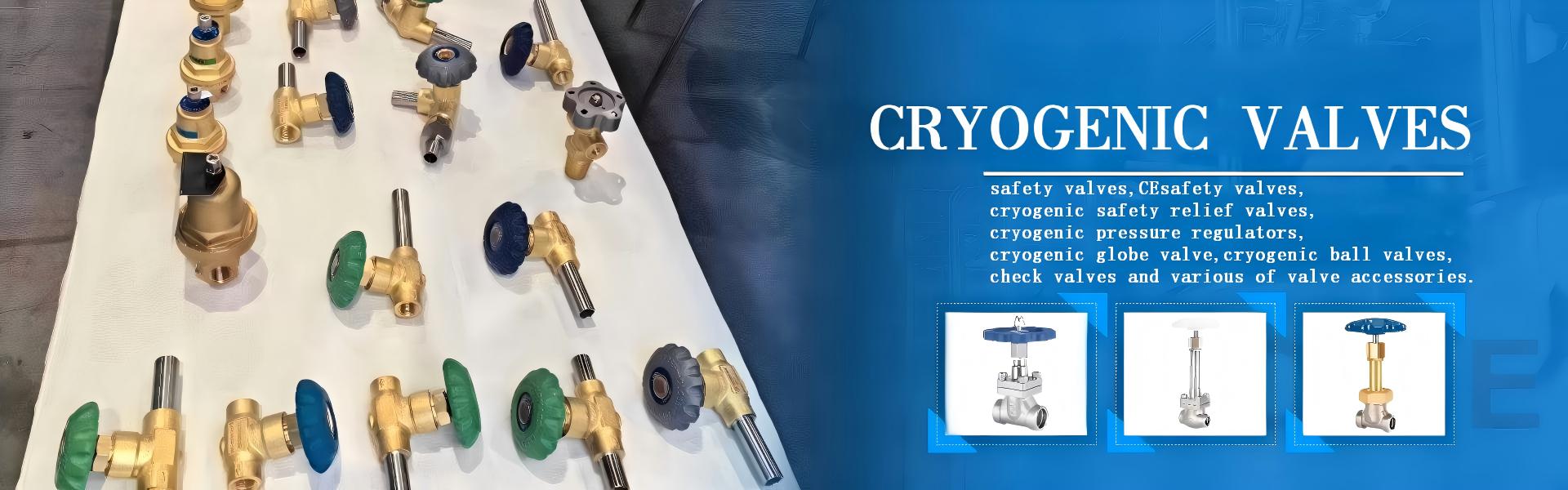
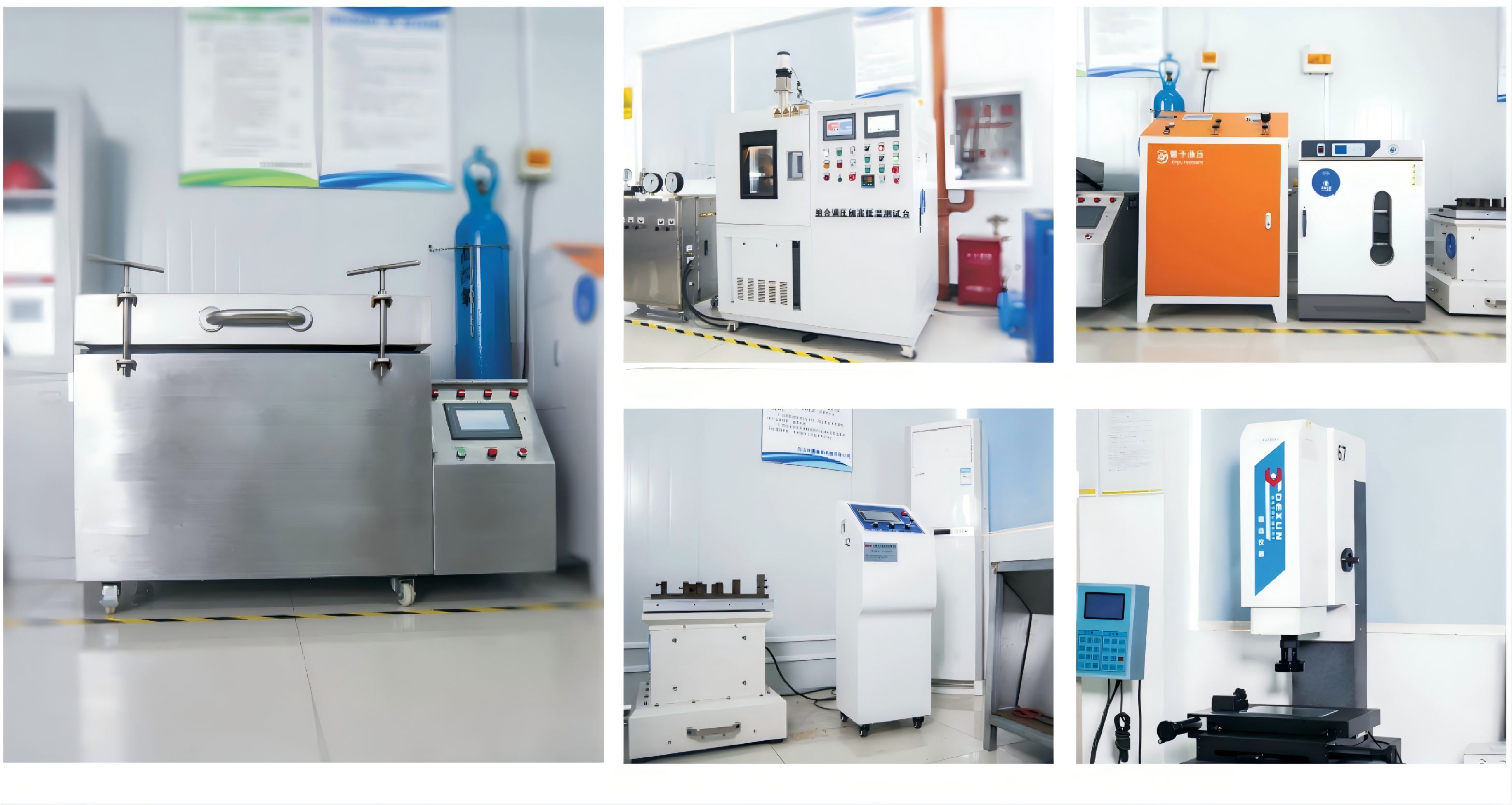
Factory Shoot


|
Application Video
|
Product parameters


| Data Sheet

|
Comment & FAQ
1: What is the fundamental difference between an economizer (DYS25A) and a pressure-building regulator (DYS15/20)?
A: The difference is which fluid they handle and what thermodynamic objective they serve. A pressure-building regulator controls liquid flow from the tank sump to an external vaporizer; its purpose is to actively increase tank pressure by vaporizing liquid and returning the gas to the headspace. An economizer controls gas flow from the vapor space directly to the downstream consumption line; its purpose is to passively limit tank pressure by bleeding off naturally accumulating boil-off vapor before the safety relief valve lifts. Confusing the two in a piping design will result in either failure to build pressure (if an economizer is installed where a PB regulator is needed) or continuous venting of liquid through the economizer (if a PB regulator is installed where an economizer should be—the PB regulator's liquid-rated disc seal will not close bubble-tight on gas). They are complementary devices that should both be present on a well-designed large cryogenic tank: the PB regulator controls the lower pressure bound (prevents tank from going sub-atmospheric during high-demand withdrawal), and the economizer controls the upper pressure bound (prevents SRV lifting during low-demand storage).
2. Why three progressive, non-overlapping ranges for the economizer, when PB regulators use overlapping ranges?
A: The tank's safety relief valve set point is a fixed design parameter. For a given tank, there is exactly one correct economizer range—the one whose upper limit sits 10–15 PSIG below that specific SRV setting. There is no operational scenario where the designer needs to "choose between A1 and A2 for the same tank," because the tank's SRV does not change. The non-overlapping, progressive split eliminates the possibility of field mis-adjustment: if a technician sets an A1 to 200 PSIG to protect a 250 PSIG SRV, the spring will reach solid height before reaching the set point, providing a hard mechanical stop that prevents the error. In a PB regulator, overlapping ranges are intentional because the operator may choose different operating pressures for the same tank depending on downstream demand.
3. Why does the DYS25A use a ball-and-seat design while DYS15/20 use disc-and-flat-seat?
A: Gas sealing demands line contact. A flat disc on a flat PTFE seat achieves a seal through area contact—the entire annular surface must be co-planar within the PTFE's compression set limit. At low gas differential pressures (5–20 PSIG, typical of the economizer's partial-lift modulation band), the specific seating pressure (force/area) may be insufficient to close the micro-roughness leakage paths. A ball on a conical seat solves this by concentrating the same spring force onto a near-zero-area contact line, producing a local contact stress high enough to deform the PTFE seal ring into the stainless surface asperities. The ball also self-centers during thermal transients; the DYS25A guide sleeve (7) maintains 20 μm concentricity, but even at 50 μm of misalignment, the ball geometry corrects itself upon contact with the 60° cone—a disc cannot do this. The downside is that ball-seat designs have lower flow coefficients (Cv) than equivalent-sized disc designs, which is why they are not used for liquid PB service where high Cv is needed to feed a vaporizer.
4. What are swivel nut connections and what torque specification applies?
A: Swivel nut connections consist of a threaded nut that rotates independently of the tube, tightening onto a male threaded boss on the valve body. The tube end is flared or fitted with a cryogenic-compatible ferrule that seals against a conical seat inside the valve port when the nut is torqued. This allows in-line installation without rotating the valve body—critical for the DYS25A's L=270 mm length in confined tank-top piping layouts. The D1 = Φ32.5 mm dimension is the nut thread outer diameter, and the D2 = 36.5 mm dimension is the hex flat for the wrench. Torque specification is 45–55 N·m for stainless-on-stainless swivel nuts in cryogenic service using a copper or nickel gasket; over-torquing above 60 N·m risks galling the stainless threads at cryogenic temperature. Always apply a cryogenic-compatible anti-seize compound (nickel-based, not copper-based for oxygen service) to the nut threads before assembly.
5. Can the DYS25A be used as a pressure-building regulator or vice versa?
A: No. The DYS25A economizer and DYS15/20 pressure-building regulators are not interchangeable for two independent reasons. First, the seal architecture: the DYS25A's ball-seat gas seal will not close reliably against liquid because the liquid's higher viscosity and surface tension create a hydrodynamic lifting force on the ball at the moment of closure, preventing the line-contact seal from establishing. Conversely, the DYS15/20's flat-disc PTFE seal designed for liquid (where a thin liquid film helps achieve zero leakage) will leak gas at the micro-roughness level of the PTFE surface. Second, the flow capacity: a PB regulator is sized for the liquid flow required by a pressure-building vaporizer (typically 5–50 L/h liquid), while an economizer is sized for the vapor flow from a tank's natural boil-off (typically 0.5–5 kg/h vapor). Installing either in the wrong service will result in either severe under-sizing or continuous leakage.
6. What is the role of the internal sensing pipe (component 10)?
A: The sensing pipe is a critical regulatory refinement absent from all DYS pressure-building regulators. In a direct-sensing design (where the diaphragm chamber is open to the valve outlet cavity), turbulence from the gas bleed flow creates pressure fluctuations of ±2–5 PSIG at the diaphragm—noise that causes the ball to dither around the set point, producing both premature seat wear and unstable downstream pressure. The sensing pipe isolates the diaphragm chamber from the turbulent flow zone by tapping pressure from a stagnation point in the outlet passage, delivering a quiescent pressure signal to the diaphragm. The C = 10 mm dimension likely represents the sensing tube wall clearance or wall thickness, ensuring the tube has sufficient mechanical stiffness to resist flow-induced vibration.

 yongy0223@gmail.com
 +86-17693104145
 Lanzhou New Area, Lanzhou City, Gansu Province, on the second floor to the east of New Harbor Road, to the east of Building Materials Road No. 2, to the west of Qilian Mountain Avenue (Jingqi Road)


