

 |


loading


DA21F-40P
SLDW
| Size: | |
|---|---|
| Availability: | |
| Quantity: | |
| Product Overview
The DA21F-40P DN25 is a spring-loaded cryogenic safety valve engineered for overpressure protection in deep-cryogenic systems operating down to −196°C. It is a compact, precision-machined pressure-relief device whose function is to open automatically when the system pressure exceeds a preset threshold, vent the excess gas, and reseat once normal pressure is restored—protecting cryogenic storage tanks, dewars, piping, and process vessels from the pressure build-up caused by boil-off, thermal expansion, or upstream over-supply.
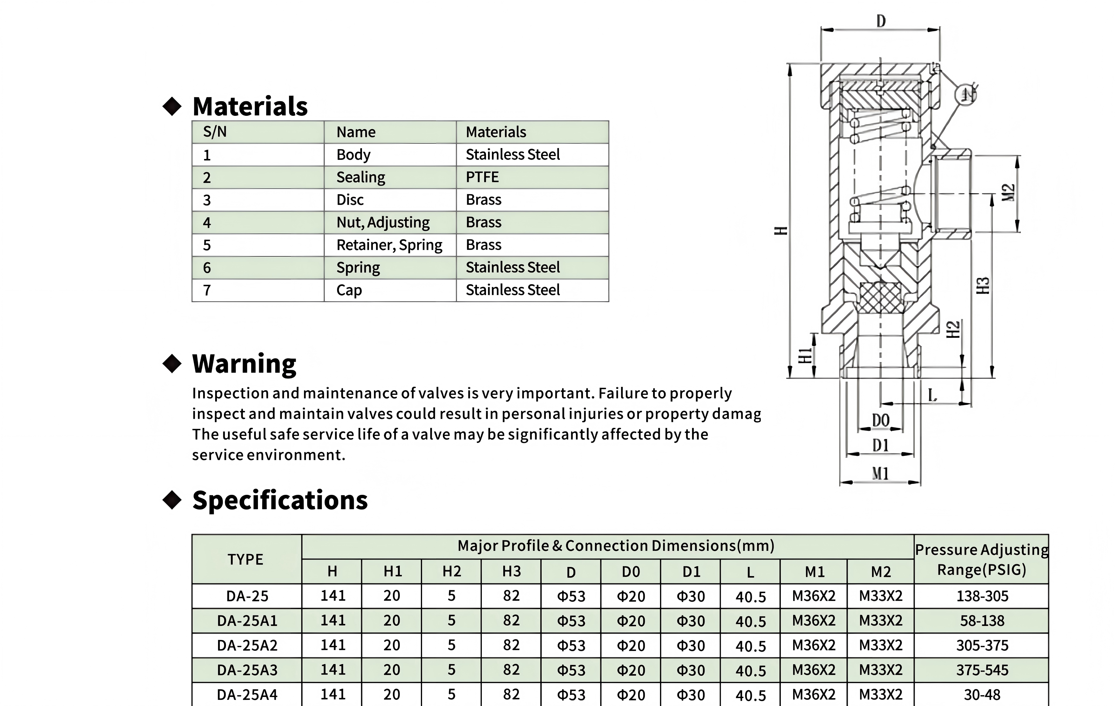
The valve body is manufactured in stainless steel, selected for its deep-cryogenic toughness and corrosion resistance across the full industrial gas spectrum—LOX (liquid oxygen), LIN (liquid nitrogen), LAr (liquid argon), and LNG (liquefied natural gas). The sealing element is a PTFE soft seat, which provides a tight, leak-free closure at cryogenic temperatures where metal-to-metal seats are prone to leakage due to differential thermal contraction. The valve carries a PN40 pressure rating (equivalent to Class 300) with a DN25 nominal bore, and the DA-25 series specification table covers a relief set-pressure range of approximately 30–545 PSIG, allowing the same valve family to be matched to different protection requirements.
Three design details distinguish this valve in field service. First, the adjustable set-pressure cap on top allows the opening pressure to be tuned to the specific protection requirement of the installation. Second, the rotatable threaded inlet and outlet connections enable compact, direct installation into a cryogenic piping system—the rotating joints allow the valve body to be oriented freely during assembly, simplifying alignment with existing pipework. Third, the bottom external-thread mounting end provides a direct, rigid connection to the pipeline, while the valve cavity's upper relief port offers an additional pressure-release path for the internal chamber.
The valve is manufactured in compliance with ISO 4126 (safety devices for protection against excessive pressure) and the Chinese national standard GB/T 29026, giving users a documented basis for acceptance in both domestic and export installations. Its spring-loaded, self-reseating design means it can be reused across repeated overpressure events without replacement—unlike frangible devices such as rupture discs—and its compact cylindrical form factor makes it well suited to space-constrained cryogenic skids and manifolds.
| Working Principle
The Closed State — Spring Preload and Sealing:
Inside the valve, a compression spring is preloaded against the valve disc (the moving closure element) through the adjustable cap on top. The spring force presses the disc down onto the PTFE seat, forming a gas-tight seal between the process side and the discharge side. The preload is set so that the downward spring force balances the upward force exerted by the process pressure acting on the disc area. At normal operating pressure—below the set point—the spring force exceeds the pressure force, and the valve remains closed with zero leakage. The PTFE soft seat is critical here: at cryogenic temperatures, metal components contract at different rates, and a rigid metal-to-metal seat can develop micro-gaps that leak. PTFE's elasticity and low-temperature compliance maintain a continuous sealing line even under differential thermal contraction.
The Opening Event — Set Point Reached:
As the system pressure rises—from boil-off accumulation, thermal expansion of trapped liquid, or upstream over-supply—the upward pressure force on the disc increases proportionally. When the process pressure reaches the set point, the upward force just equals the spring preload. Any further increase overcomes the spring, lifting the disc off the seat. The valve opens and the excess gas is discharged through the outlet connection, which is oriented to vent safely away from personnel. Because the disc lifts progressively with pressure, the valve provides a controlled, proportional release rather than an all-or-nothing burst.
The Reseating Event — Pressure Restored:
Once the overpressure condition is relieved and the system pressure falls back below the set point, the spring force again exceeds the pressure force, and the disc is pushed back onto the PTFE seat. The valve closes automatically and re-establishes the gas-tight seal. This self-reseating behavior is the defining advantage of a spring-loaded safety valve: it can protect against repeated overpressure events over its service life without replacement, and it vents only the minimum amount of gas required to restore safe pressure.
Set-Point Adjustment:
The opening pressure is determined by the spring preload, which is adjusted via the cap on top. Turning the cap compresses or relaxes the spring, raising or lowering the set point within the valve's rated range (approximately 30–545 PSIG across the DA-25 series). This allows a single valve model to be field-tuned to different protection requirements, though in practice the set point is typically locked and tagged after factory calibration to prevent unauthorized tampering.
Installation-Oriented Design:
The rotatable threaded inlet and outlet connections allow the valve to be installed without imposing torsional stress on the body—the joints rotate to align with the pipework while the body remains stationary. The bottom external-thread mounting end provides a rigid, direct connection to the pipeline, and the valve cavity's upper relief port protects the internal chamber from trapped-pressure build-up. Together, these features ensure that the valve's spring preload and set point are not disturbed by installation forces, preserving calibration accuracy in the field.

|
Factory Shoot


|
Application Video
|
Product parameters


| Data Sheet
|
Comment & FAQ
1: What do DN25 and PN40 mean?
A: DN25 is the nominal bore (nominal diameter) of the valve—approximately 25 mm—which determines the size of the flow passage and the connection dimensions. PN40 is the nominal pressure rating, indicating the valve is designed for a nominal working pressure of about 40 bar (equivalent to Class 300 in the ANSI system). Together they define the valve's size and pressure capability: DN25 tells you which pipe size it fits, and PN40 tells you the pressure class of the system it can serve. The actual relief set pressure is a separate parameter, adjustable within the valve's rated range (approximately 30–545 PSIG across the DA-25 series).
2. What does the model DA21F-40P mean?
A: The model number is a manufacturer's code for the valve's structure, sealing form, and pressure rating. "DA" typically denotes the cryogenic safety valve series, "21" denotes the spring-loaded structure type, "F" denotes soft sealing (PTFE seat), "40" denotes the nominal pressure rating (corresponding to the PN40 system, i.e., a nominal pressure of about 40 bar), and "P" denotes a stainless steel valve body. Note that coding conventions may vary slightly between manufacturers, so always confirm against the manufacturer's model description and datasheet when purchasing.
3. What is the adjustable cap on top for?
A: The cap on top adjusts the spring preload, which determines the valve's opening (set) pressure. Turning the cap clockwise compresses the spring and raises the set point; turning it counter-clockwise relaxes the spring and lowers the set point, within the valve's rated range. This allows a single valve model to be field-tuned to different protection requirements. In practice, however, the set point is typically locked and tagged after factory calibration to prevent unauthorized tampering. If your process requires a different set pressure, it is recommended to specify it at the time of purchase and have the manufacturer calibrate it at the factory.
4. Does it require regular maintenance and calibration? How often?
A: Yes. As a safety-critical device, it should be maintained on a regular schedule: (1) Functional testing—periodically (e.g., quarterly or per plant safety policy) verify that the disc moves freely and reseats with a good seal; (2) Set-pressure calibration—annually or per local regulation, verify on a test bench that the actual opening pressure is still within the allowed tolerance of the set value, and recalibrate if out of range; (3) Visual and seal inspection—check the body for corrosion, icing, external damage, and any signs of leakage at the connections; (4) Seal replacement—the PTFE seat may wear after long service or repeated actuation; replace per the manufacturer's recommended interval. After maintenance, recalibrate, seal, and record. The specific interval should follow local pressure-vessel/piping safety regulations and the manufacturer's maintenance manual.
5. What should I pay attention to during installation?
A: Key installation points include: (1) connect via the bottom external-thread mounting end, ensuring a tight joint with sealing material suitable for cryogenic service; (2) orient the outlet connection toward a safe area so that vented gas is directed away from personnel, equipment, and heat sources, adding a discharge line if necessary; (3) take advantage of the rotatable threaded connections to align the valve without imposing torsional stress on the body—the joints rotate while the body stays stationary, preserving calibration; (4) position the valve so the top cap and any test features remain accessible for maintenance; (5) do not install an isolation valve upstream that could block pressure transmission (or interlock it per code), otherwise overpressure protection is weakened; (6) provide cryogenic protection for the body and connections to prevent icing from affecting operation.

 yongy0223@gmail.com
 +86-17693104145
 Lanzhou New Area, Lanzhou City, Gansu Province, on the second floor to the east of New Harbor Road, to the east of Building Materials Road No. 2, to the west of Qilian Mountain Avenue (Jingqi Road)


