

 |


loading


DQS15F
SLDW
| Size: | |
|---|---|
| Availability: | |
| Quantity: | |
| Product Overview
The DJC40 / DJC40B is a cryogenic combination fill & drain valve — an integrated fill manifold engineered for the filling, draining, and pressure-building operations of deep-cryogenic storage systems. Unlike a single-function valve, it combines several operating functions in one body (a true multi-valve combination module with four valve functions, including a dedicated bottom fill valve), so a cryogenic storage vessel can be filled, drained, pressure-built, and vapor-balanced through one compact, flanged manifold connection. It is designed for large cryogenic storage vessels and tank systems handling LOX, LIN, LAr, and LNG, in service from −196°C to +74°C at working pressures up to 580 PSI (40 bar).
The manifold is built for corrosion resistance, cryogenic toughness, and long service life: the 304/316 stainless steel construction resists the corrosive, high-purity media of the industrial gas industry, while the robust bolted stainless steel bonnet and stem provide reliable sealing and smooth operation down to −196°C. Flanged connections accept mating pipework on large vessel installations, with customizable connection sizes available to match specific tank neck configurations.
Two features define its field practicality. First, the self-draining strainer within the manifold filters the cryogenic medium while automatically draining accumulated liquid, preventing static-charge-related and ice-induced clogging that could otherwise block the fill/drain passage in low-temperature service. Second, the integrated vapor-balance/vent port at the top of the module is used for gas-phase equalization or venting during transfer operations, stabilizing pressure and reducing flash-gas losses while filling or draining.
Operation is fully manual: the operator opens and closes the individual functions with the top-mounted hand wheels, controlling filling, draining, and pressure-building directly from the vessel connection point. Quality and safety are assured—every valve is 100% factory tested and manufactured in accordance with the Chinese cryogenic equipment standards GB/T 24925 and GB/T 12235, and it is available with CGA G-4.1 oxygen-service cleaning for oxygen and medical-oxygen filling applications where cleanliness and material compatibility are critical.
| Working Principle
A combination fill & drain valve is a multi-function manifold that routes several cryogenic-tank operations through a single body. Its core concept is that the same vessel opening is shared by multiple individually controlled passages, each dedicated to one operation (filling, draining, pressure building, vapor balance), arranged in one integrated module. The DJC40 / DJC40B realizes this with four valve functions combined in one flanged body, operated manually through the top hand wheels.
The Filling Principle (Bottom Fill):
During filling, the operator opens the bottom fill valve passage. Liquid cryogen is introduced at the bottom of the tank while the vessel's vapor space is vented or balanced through the top vapor port. Filling from the bottom minimizes flash-gas generation: the incoming liquid contacts the liquid already in the tank rather than splashing into a hot vapor space, which would boil off as flash gas and cause pressure spikes and product loss. The self-draining strainer in the fill passage filters particulate from the incoming medium; its self-draining design prevents liquid from pooling and freezing into ice that could clog the passage, while its construction also mitigates blockage caused by static-charge attraction of particles in cryogenic flow. As filling proceeds, the operator monitors the level and closes the fill valve when the tank reaches the target fill level.
The Draining Principle:
When liquid must be withdrawn, the operator opens the drain passage (one of the lower outlets). The liquid is driven out of the tank by the tank's internal pressure (the pressure-building circuit keeps the vapor space pressurized) and flows through the drain connection to the downstream equipment. The manifold's integrated design lets the operator switch between filling and draining at the same vessel connection without re-piping, which is especially convenient on storage vessels where connections are limited and repeated over long service life.
The Pressure-Building and Vapor-Balance Principle:
Two auxiliary functions complete the combination. First, the vapor/withdrawal connections allow the tank's pressure-building circuit to be connected: liquid is drawn off, vaporized, and returned to the vapor space to maintain the operating pressure that drives draining and dispensing. Second, the top vapor-balance/vent port equalizes or vents the gas phase: during filling, it vents the displaced vapor or connects to a vapor-return line to balance pressure with the source tank; during draining or pressure building, it can serve as the vent path. Controlling vapor flow through this port stabilizes tank pressure, reduces flash-gas losses, and prevents over-pressurization during transfer operations.
The Integral Multi-Valve Control Principle:
Because the four functions share one integrated body and are isolateable by individual hand wheels, the operator builds the required flow configuration by opening only the needed functions and keeping the others closed. This "combination" approach is the essence of the design: one connection point, multiple controlled operations—reducing tank neck openings, leak points, and piping complexity, while enabling filling, draining, pressure building, and vapor balancing through a single flanged manifold. Manual hand-wheel operation gives the operator direct, predictable control of each function at the vessel.
Leak-Proof Sealing and Safe Operation at Cryogenic Temperature:
At −196°C, reliable sealing depends on stainless bonnet-to-body joints and stems engineered for differential thermal contraction. The bolted stainless bonnet and stem hold consistent stem seal preload through thermal cycling, keeping the open/closed state leak-tight. Every operation is verified by 100% factory testing, and the fill manifold is produced to GB/T 24925, GB/T 12235, and the CGA G-4.1 oxygen-cleaning standard where required, so the combination valve can be relied upon for safe, leak-free filling and draining of LOX, LIN, LAr, and LNG vessels.

|
Factory Shoot


|
Application Video
|
Product parameters


| Data Sheet
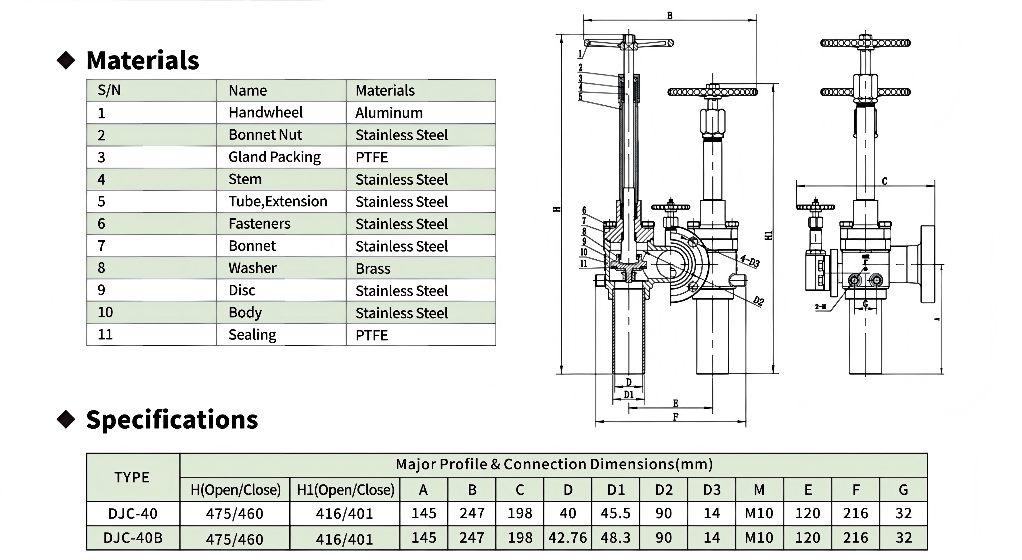
|
Comment & FAQ
1: What is the DJC40 / DJC40B and what does "combination fill & drain" mean?
A: The DJC40 / DJC40B is a cryogenic combination fill & drain valve — an integrated fill manifold for large cryogenic storage vessels. "Combination fill & drain" means it combines several tank operations in a single flanged body: a true multi-valve module with four valve functions (including a dedicated bottom fill valve) that can fill, drain, pressure-build, and vapor-balance a cryogenic tank through one connection point. Instead of mounting several separate valves on different vessel nozzles, the operator uses one integrated manifold and controls each function with its own hand wheel. This reduces tank neck openings, leak points, piping, and installation cost, and is especially suited to large LOX/LIN/LAr/LNG storage vessels in continuous service from −196°C to +74°C at up to 580 PSI (40 bar).
2. What does "bottom fill" mean and why fill from the bottom?
A: The bottom fill valve introduces liquid cryogen at the bottom of the tank rather than spraying it into the vapor space at the top. Filling from the bottom has three advantages. First, it reduces flash-gas generation: incoming liquid contacts the cool liquid already in the tank instead of splashing into a warm vapor space, so far less of the incoming liquid boils off as flash gas. Second, it reduces pressure spikes and product loss: less vaporization means less pressure rise and less vented product. Third, it improves fill efficiency and controllability, letting the operator fill to the target level quickly and predictably. On large cryogenic storage vessels, bottom filling through a dedicated fill valve is the standard method for efficient, low-loss liquid loading.
3. What is the self-draining strainer and why is it important?
A: The self-draining strainer is a filter element built into the manifold's fill/drain passage that removes particulate from the cryogenic medium while automatically draining any liquid that accumulates in the filter housing. It is important for two reasons specific to cryogenic service. First, in low-temperature flow, liquid can pool in a filter housing and freeze into ice that progressively clogs the passage—a self-draining design prevents this by continuously draining the accumulated liquid. Second, cryogenic flow can generate static charge, which attracts particles and worsens clogging; the strainer's construction mitigates static-attraction buildup so the fill/drain path stays clear. Together, these features protect flow capacity and reliability on large filling operations where a blocked passage would otherwise interrupt loading.
4. What are the typical applications of the DJC40 / DJC40B?
A: Typical applications include: bottom filling and draining of large cryogenic storage vessels for LOX, LIN, LAr, and LNG; cryogenic tank loading and unloading in bulk supply stations and gas plants; pressure-building connections where liquid is withdrawn, vaporized, and returned to maintain operating pressure; vapor balancing during transfer between a source tank and a receiving vessel; and oxygen/medical-oxygen filling applications, thanks to the available CGA G-4.1 oxygen-service cleaning. It is a fit wherever a cryogenic tank needs one flanged connection that performs filling, draining, pressure building, and vapor balance in a single integrated manifold—typically on vessel and tank systems from −196°C to +74°C at up to 580 PSI (40 bar).
5. What standards is the valve manufactured to?
A: The DJC40 / DJC40B is manufactured in accordance with GB/T 24925 (the Chinese standard for cryogenic valve general specifications) and GB/T 12235 (the Chinese standard for steel flanged gate, globe, check, and similar valve structures in petrochemical service). It is also available with CGA G-4.1 oxygen-service cleaning for oxygen and medical-oxygen applications, and every valve is 100% factory tested. In practice this combination means the manifold is produced to Chinese national cryogenic-equipment requirements with an option for international oxygen-service cleanliness, giving designers and operators a compliant, qualified connection component for cryogenic storage vessel fills. Where your project requires additional standards (e.g., international equivalents), confirm the applicable options with the manufacturer.
6. How is the valve installed on a cryogenic vessel?
A: The manifold is provided with flanged connections for direct mounting to the mating flange of a cryogenic storage vessel neck or piping, and customizable connection sizes are available to match specific tank configurations. Installation generally proceeds as follows: (1) verify the flange gasket, bolting, and torque are suitable for cryogenic service and the working pressure; (2) align the manifold without imposing bending or torsional stress, and support the valve and adjacent piping; (3) connect the fill, drain, pressure-building, and vapor-balance/vent lines to their corresponding ports, confirming each line goes to the correct function; (4) confirm the hand wheels are accessible and each function's open/closed direction is identified; (5) before first use, perform a leak test and functional test per the manufacturer's procedure. For oxygen service, observe CGA G-4.1 cleanliness during handling and installation.

 yongy0223@gmail.com
 +86-17693104145
 Lanzhou New Area, Lanzhou City, Gansu Province, on the second floor to the east of New Harbor Road, to the east of Building Materials Road No. 2, to the west of Qilian Mountain Avenue (Jingqi Road)


